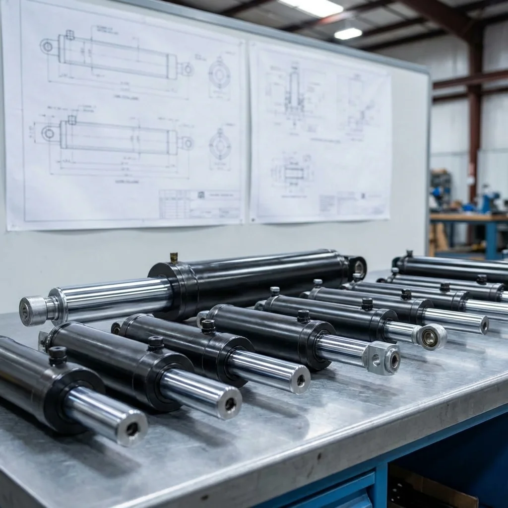
A hydraulic accumulator is a pressure vessel that performs multiple
tasks
in a hydraulic system.
It is used to maintain pressure, store and recapture energy, reduce pressure peaks,
power
chassis suspensions,
and dampen shock, vibration, and pulsations.
Ideal Gas Law (Boyle's Law)
P₀ × V₀ = P₁ × V₁
Describes the compression of gas (Nitrogen)
within the accumulator.
1. Main Functions
- Energy Storage:
Stores potential energy to supplement pump flow.
- Emergency
Power:
Provides energy during power failure.
- Shock
Absorption:
Dampens hydraulic hammer effects.
- Leakage
Compensation: Maintains system pressure during holding cycles.
2. Accumulator Types
Selecting the right type depends on the application volume, response time, and flow rate
requirements.
2.1. Bladder Accumulators
Consists of a flexible rubber bladder inside a steel shell. The bladder contains the
gas,
and the shell contains the fluid.
Benefits: Fast response time, good resistance to contamination.
2.2. Diaphragm Accumulators
Uses a flexible diaphragm to separate gas and fluid.
Benefits: Compact size, lightweight, low cost, ideal for mobile
equipment.
2.3. Piston Accumulators
Uses a floating piston as a separator.
Benefits: High flow rates, high temperature tolerance, very large
volumes
possible.
| Type |
Response Time |
Pressure Ration |
Typical Volume |
|
Bladder |
Very Fast (< 25ms) |
4:1 |
1L - 50L |
|
Diaphragm |
Fast |
8:1 |
0.075L - 4L |
| Piston |
Slow (> 25ms) |
N/A |
Up to 2500L |
3. Pre-Charging (Nitrogen)
"Correct pre-charge pressure (P₀) is critical. For energy storage, P₀ is typically
set
to 90% of the minimum system operating pressure (P₁)."
— BRS PROSES Engineering Team
Warning: Accumulators must only be charged with inert gas, typically
dry Nitrogen. Never use Oxygen or Air, as this poses an explosion
hazard!
4. BRS PROSES Accumulator Services
We provide complete accumulator solutions including supply, installation, and
certification.
- Accumulator sizing and
calculation
- Nitrogen pre-charging services
- Bladder replacement and repair
- Safety block and mounting kit
supply
- Regular maintenance and
inspection
6. Thermodynamics of Nitrogen Gas Expansion: Isothermal vs. Adiabatic
Hydraulic accumulators store fluid energy via compressible nitrogen gas separation bladders, diaphragms, or pistons. Sizing accumulator capacity requires calculating gas volume changes between minimum working pressure ($P_1$) and maximum working pressure ($P_2$):
P_0 \cdot V_0^n = P_1 \cdot V_1^n = P_2 \cdot V_2^n \quad \text{with} \quad \Delta V = V_1 - V_2
- Isothermal Expansion ($n = 1.0$): Applicable when compression or expansion occurs slowly ($t > 3 ext{minutes}$), allowing complete heat dissipation through the steel shell to ambient air.
- Adiabatic Expansion ($n = 1.4$ for Diatomic Nitrogen): Applicable for rapid emergency discharge cycles ($t < 3 ext{seconds}$). Gas cools rapidly during expansion, requiring significantly larger accumulator shell volumes to deliver the specified fluid volume ($Delta V$).
7. European Pressure Equipment Directive (PED 2014/68/EU) & Safety Blocks
Because hydraulic accumulators store explosive potential energy under pressures exceeding 300 bar, international safety directives mandate dedicated safety and shut-off manifold blocks (BSB):
| Mandatory Safety Element |
Compliance Directive |
Critical Life-Safety Function |
| TÜV/CE Certified Pressure Relief Valve |
PED 2014/68/EU Category IV |
Guaranteed blow-off capacity preventing shell overpressure rupture |
| Manual / Solenoid Tank Bleed Valve |
EN ISO 4413 Safety Standard |
Depressurizes stored oil volume to reservoir prior to maintenance |
| Bursting Disc / Thermal Fuse Plug |
ISO 9809 Gas Cylinder Norm |
Releases nitrogen gas safely to atmosphere in the event of plant fire |
Thermodynamic Accumulator Sizing: Isothermal vs Adiabatic Nitrogen States
Hydro-pneumatic accumulators store potential energy by compressing nitrogen gas ((N_2)) behind an elastomeric bladder, flexible diaphragm, or floating piston. Sizing an accumulator requires knowing whether the discharge cycle is slow enough to exchange heat with the surrounding environment (isothermal expansion, (n = 1.0)) or rapid and explosive (adiabatic expansion, (n = 1.4) for diatomic nitrogen).
1. Universal Gas Law Governing Accumulators
P_0 × V_0^n = P_1 × V_1^n = P_2 × V_2^n
• P_0: Nitrogen pre-charge pressure (bar)
• P_1: Minimum working pressure at end of discharge (bar)
• P_2: Maximum working pressure after pump charging (bar)
• V_0: Total internal shell volume of accumulator (Liters)
2. Bladder Protection Rules & Pre-Charge Benchmarks
The 90% Rule for Energy Storage: Set nitrogen pre-charge (P_0) to 90% of minimum system pressure ((P_0 = 0.9 imes P_1)). Setting (P_0) too high causes the rubber bladder to strike the bottom anti-extrusion poppet valve during discharge, tearing the elastomer. Setting (P_0) too low (< (0.25 imes P_2)) causes excessive bladder folding and structural fatigue.
Safety Dump Block Mandate: In accordance with ISO 4413 and PED 2014/68/EU, every accumulator must be equipped with an integrated safety block containing a certified burst disc/relief valve and a manual or solenoid-operated discharge valve to safely bleed trapped pressure before maintenance.
Technical Field Inspection & Commissioning Protocol
Prior to signing off on any fluid power retrofit, system upgrade, or routine component overhaul, technical commissioning engineers must rigorously complete the following verification procedures to ensure full compliance with ISO machinery safety standards:
- Static Hydrostatic / Pneumatic Pressure Proof Test: Pressurize circuit to 1.5× maximum design working pressure for 15 minutes, inspecting all welded flanges and fittings for micro-weeping.
- Contamination & Fluid Particle Verification: Draw dynamic fluid samples under working temperature and confirm ISO 4406 cleanliness classes (or ISO 8573-1 air dew point classes) before activating sensitive proportional spool valves.
- Thermal Baseline Profiling: Record continuous thermal infrared scans of pump casings, valve manifold manifolds, and accumulator bodies across 4 hours of full-load production cycles to confirm proper thermal dissipation.
- Failsafe & Emergency De-energization: Verify manual LOTO isolation valves, dump valves, and accumulator vent blocks discharge trapped hydraulic/pneumatic kinetic energy to 0 bar within 2.0 seconds of emergency e-stop triggering.