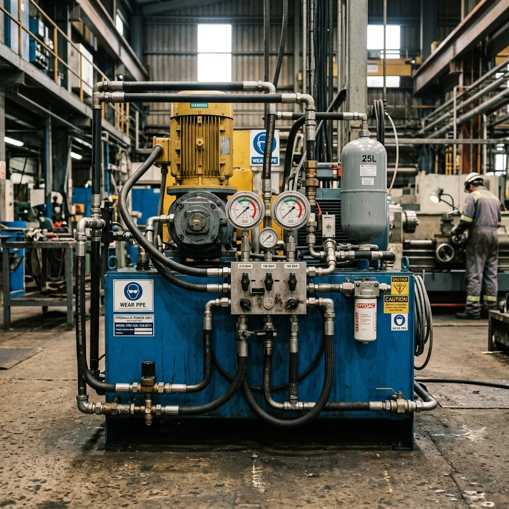
A few drops of hydraulic oil pooling on a workshop floor look like a minor cosmetic issue. In reality, it's often the first sign that pressure is escaping somewhere in the system - and that efficiency is dropping with it.
Two Leak Types
Static: between two fixed surfaces (flange, cover) | Dynamic: at a moving surface (piston rod, shaft)
1. Where the Leak Comes From
1.1. Static Leaks
Usually caused by hardened seals, incorrect torque, or dirt buildup on the surface; easy to spot because the source stays fixed.
1.2. Dynamic Leaks
Occurs between a moving surface (piston rod or shaft) and its seal. Every motion cycle wears the seal surface microscopically, so a dynamic leak is a problem that worsens gradually.
| Seal Material | Typical Life | Oil Compatibility | Risk Condition |
|---|
| Standard NBR | 8-10 years | Mineral hydraulic oil | Above 120°C, acid vapor |
| Viton (FKM) | 10-15 years | Wide range | Very low temperature (below -20°C) |
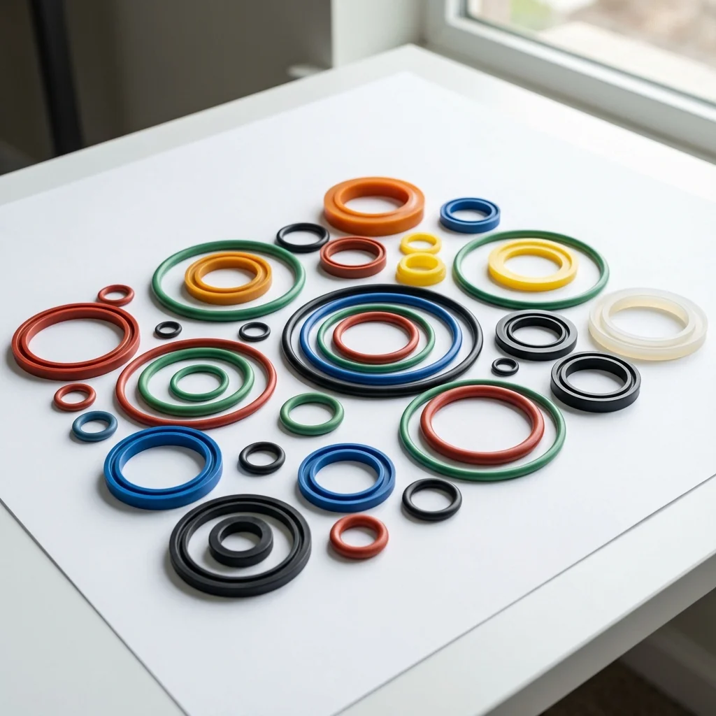
| Polyurethane | 5-8 years | High-pressure dynamic | Abrasive particle contamination |
2. Typical Causes
- Wrong Seal Choice: an elastomer incompatible with the oil type swells or hardens within months
- Material Aging: standard NBR seals start losing flexibility after 8-10 years even without visible failure
- Hose Loosening: fitting connections loosen over time in vibrating environments, and torque deviation starts micro-leaks
"Finding and fixing the source of a leak, rather than just wiping it away, saves both oil cost and the downtime a hydraulic failure would cause."
— BRS PROSES Engineering Team
3. Prevention and BRS Proses Support
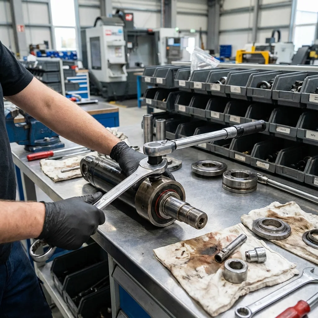
Keeping torque values consistent with manufacturer tables and choosing seals matched to oil type prevents most leaks before they start:
- On-site leak source diagnosis
- Seal material recommendation matched to oil type
- Contamination control via ISO 4406 particle counting
- Periodic torque and seal-life scheduling
6. SAE J518 / ISO 6162 Code 61 & Code 62 Flange Standards
Threaded tapered pipe fittings (NPT/BSPT) represent the leading historic cause of hydraulic leaks, relying on thread deformation and chemical sealant pastes that degrade under dynamic pressure pulsations. Modern high-pressure hydraulic architectures eliminate threaded ports entirely, transitioning to SAE 4-bolt split flange connections (ISO 6162):
- ISO 6162-1 (SAE Code 61 - Standard Pressure): Rated for pressures up to 350 bar (depending on port size). Utilizes an elastomeric O-ring trapped within an engineered annular groove on the flange face, tightened via four high-tensile Grade 10.9 hex cap screws.
- ISO 6162-2 (SAE Code 62 - High Pressure): Engineered with thicker flange clamp collars and deeper bolt thread engagement to withstand continuous cyclic pressures up to 420 bar without bolt stretching or flange bending fatigue.
7. DIN 2353 Bite-Type Fittings: Over-Tightening vs. Walform Flaring
In tube-to-valve connections, standard DIN 2353 cutting ring (bite-type) fittings frequently leak when maintenance technicians over-tighten the coupling nut. Over-torquing shears the front cutting edge of the ring, crushing the thin-walled seamless tube and inducing micro-gaps.
| Connection Technology |
Pressure Rating |
Vibration Fatigue Resistance |
Leakage Prevention Protocol |
| DIN 2353 Bite-Type (24° Cone) |
Up to 400 Bar |
Moderate (Vibration sensitive) |
Mandatory pre-assembly tool + calibrated torque wrench |
| Walform Tube Reshaping |
Up to 630 Bar |
Extremely High (Positive lock) |
Cold-formed tube profile with captive elastomeric O-ring |
| 37° Flare Flange (DIN EN ISO 8434-2) |
Up to 420 Bar |
Maximum (Zero notch effect) |
No welding cinders, orbital pipe expansion, weld-free assembly |
Zero-Leakage Engineering: Fitting Architecture, Torque Standards & Thermal Vibration
Hydraulic fluid leakage is not an inevitable byproduct of high-pressure fluid power; it is an engineering defect caused by improper fitting selection, vibration loosening, or dynamic pressure pulsations. Modern hydraulic architectures eliminate outdated NPT pipe threads in favor of elastomeric O-ring face seal fittings (ORFS) to guarantee zero environmental emissions.
1. Fitting Standards Comparison: NPT vs DIN 2353 vs SAE J1453 (ORFS)
- NPT / BSPT (Tapered Thread): Relies on thread deformation and PTFE tape for sealing. Highly susceptible to cracking upon overtightening and prone to weeping under thermal cycles. Strictly prohibited in modern high-pressure machinery.
- DIN 2353 Metric Bite-Type (Cutting Ring): Excellent mechanical grip on hard hydraulic tubing. However, over-torquing during assembly can crush the tube wall, while under-torquing leads to tube pull-out under pressure surges.
- SAE J1453 O-Ring Face Seal (ORFS): Features a machined flat face enclosing an elastomeric O-ring compressed against a flanged tube end. Provides exceptional resistance to vibration loosening, unlimited reusability, and zero leakage up to 420 bar.
2. Flexible Hose Routing & Minimum Bend Radius Rules
Over 40% of hydraulic hose failures occur within 50 mm of the end crimp fitting due to torsional twisting or violating minimum bend radius (MBR) ratings under dynamic pressure surges. Hydraulic hoses shorten by 2% to 4% under full working pressure; therefore, all flexible lines must be routed with sufficient slack and secured using polyurethane damping clamps (DIN 3015) to absorb hydraulic pressure spikes.