Throughout every epoch of modern industrialization, hydraulic systems have reigned supreme as the quintessential source of brute force, power density, and mechanical robustness. In heavy manufacturing, aerospace, marine engineering, and metal processing, no alternative technology delivers equivalent power-to-weight ratios or handles multi-ton dynamic loads with comparable mechanical stability. However, under the rapid ascent of Industry 4.0, the role of fluid power is undergoing a radical paradigm shift. Traditional hydraulic machinery—historically perceived as isolated, purely mechanical muscles operating in isolation—is transforming into connected, cyber-physical ecosystems. Through high-precision sensor integration, edge computing, Industrial Internet of Things (IIoT) fieldbuses, and algorithmic predictive maintenance, modern smart hydraulics actively communicate their operational state, dynamically regulate energy consumption, and forecast mechanical failures long before operational disruption occurs.
What Are the Core Architectural Pillars of Smart Hydraulic Systems?
Transforming a conventional hydraulic circuit into a smart cyber-physical system requires far more than mounting an external display or logging raw pressure data to an offsite server. Genuine smart hydraulics establishes a closed-loop intelligence cycle: continuous real-time sensing, localized edge data processing, algorithmic health anomaly detection, and closed-loop electro-hydraulic actuation. Rather than relying on intermittent manual inspections with analog manometers, smart systems capture microsecond-level physical phenomena occurring within the fluid matrix.
To achieve reliable diagnostics, smart hydraulic power units (HPUs) and multi-axis actuator systems integrate four foundational sensory arrays:
- High-Frequency Dynamic Pressure Transducers: Standard industrial transmitters sample at 10–50 Hz, which is adequate for displaying steady-state pressure on an HMI but blind to hydraulic shocks. Smart piezo-resistive and thin-film transducers operate at sampling frequencies of 5 kHz to 10 kHz with response times under 0.5 ms. This microsecond resolution allows the controller to detect hydraulic water hammer, pressure pulsation harmonics generated by damaged pump pistons, and micro-cavitation transients that erode valve spools.
- Continuous Moisture & Dielectric Oil Degradation Sensors: Water contamination in hydraulic mineral oils leads to rapid additive depletion, accelerated oxidation, and catastrophic loss of lubricating film strength. Capacitive moisture sensors continuously measure relative water saturation (% RH) and absolute moisture content in parts per million (ppm). Paired with dielectric permittivity monitors, these sensors detect thermal breakdown, acid number increase, and unauthorized oil cross-contamination in real time.
- Inline Laser Optical Particle Counters (ISO 4406 / NAS 1638): Over 75% of hydraulic component failures stem from particulate contamination. Smart inline optical counters utilize laser diode extinction technology to count and classify solid particulates across calibrated channels (≥4 µm, ≥6 µm, ≥14 µm per ISO 4406:1999). Immediate detection of particle spikes serves as an undeniable signature of internal pump cavitation, cylinder barrel scoring, or filter bypass valve rupture.
- Triaxial High-Bandwidth Accelerometers & Acoustic Emission Sensors: Piezoelectric vibration sensors mounted directly on pump bearing housings and manifold blocks detect mechanical imbalance, shaft misalignment, and bearing raceway spalling. High-frequency acoustic emission sensors (100 kHz – 1 MHz) capture stress waves emitted during early-stage metal-to-metal contact, identifying lubrication starvation hours before temperature rises or audible noise develops.
Architectural Foundation: Localized Edge Computing vs. Raw Cloud Ingestion
Streaming raw sensor telemetry from dozens of 10 kHz transducers directly to cloud data centers consumes excessive network bandwidth, increases cloud storage costs exponentially, and introduces unacceptable transmission latencies (50–200 ms). In critical fluid power circuits, an overpressure spike or runaway cylinder must be mitigated within milliseconds. Modern smart hydraulics overcomes this bottleneck via Edge Computing Gateways installed adjacent to the hydraulic power pack. Industrial microcontrollers run embedded Fast Fourier Transform (FFT) algorithms, digital filtering, and localized anomaly inference directly on fieldbus modules (IO-Link v1.1, EtherCAT, PROFINET IRT, OPC UA). Only synthesized condition indices, spectral peak anomalies, and actionable maintenance triggers are transmitted upward to supervisory SCADA and enterprise cloud databases.
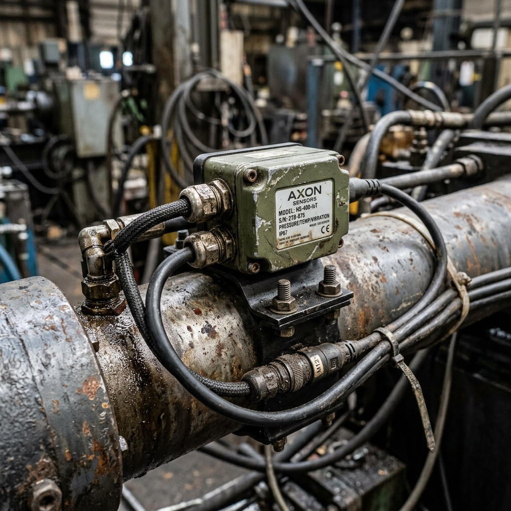
Figure 1: Heavy-duty industrial hydraulic cylinder equipped with integrated smart linear position transducers and wireless condition monitoring telematics.
How Does Non-Invasive Digital Retrofit Modernize Legacy Hydraulic Systems?
A pervasive misconception in manufacturing is that Industry 4.0 necessitates scrapping existing hydraulic infrastructure in favor of brand-new machines. In capital-intensive sectors such as steel manufacturing, automotive stamping, injection molding, and heavy forging, primary hydraulic presses and power units represent multi-million-euro investments designed for 25–40 years of service life. Replacing functional structural steel, heavy tie-rod cylinders, and hydraulic reservoirs simply to gain data visibility is economically unviable.
The engineering answer is Non-Invasive Digital Retrofitting. At BRS PROSES, we engineer retrofit packages that overlay advanced sensing and telemetry onto existing machinery with zero structural disruption:
- Minimess Test Point Interfacing: Existing diagnostic test couplings (Minimess 1215, 1620, or ISO 15171-2) are converted into continuous digital sensor nodes using miniature multi-sensor blocks measuring pressure, temperature, and flow simultaneously without depressurizing or draining the system.
- External Clamp-On Ultrasonic Flowmeters: Non-intrusive transit-time ultrasonic transducers clamp directly onto rigid steel piping (DIN 2391 / EN 10305-4). They measure instantaneous volumetric flow rates without pipe cutting, welding, pressure drops, or fluid leakage risks.
- Parallel Control Architecture: Retrofit edge loggers operate on an isolated electrical bus, tapping power from auxiliary 24V DC supplies. The diagnostic network operates in parallel with the machine's legacy relay logic or vintage PLC, ensuring that diagnostic telemetry cannot disrupt machine safety interlocks.
Predictive Maintenance (PdM) vs. Traditional Reactive & Preventive Maintenance
Industrial maintenance has historically oscillated between two suboptimal extremes: reactive "run-to-failure" maintenance and calendar-based preventive maintenance. In high-output manufacturing lines, run-to-failure results in catastrophic unplanned downtime, destroyed tooling, and tens of thousands of euros lost per hour. Conversely, preventive maintenance replaces expensive hydraulic fluids, proportional valves, and precision seal packs according to arbitrary operating hours, discarding components that possess substantial remaining operating life.
Smart hydraulics unlocks Predictive Maintenance (PdM) driven by real-time physics-informed algorithms and machine learning:
| Engineering Dimension |
Conventional Hydraulic System |
Industry 4.0 Smart Hydraulic Architecture |
Governing Standard / Protocol |
| Data Acquisition |
Manual analog dial gauges; periodic lab fluid sampling |
Inline microsecond telemetry; continuous laser particle counts |
ISO 4406 / IO-Link v1.1 |
| Maintenance Strategy |
Reactive breakdown repair or calendar-based overhaul |
Predictive Remaining Useful Life (RUL) estimation |
ISO 13374 (Condition Monitoring) |
| Motor & Pump Control |
Constant speed induction motor; relief valve throttling |
Variable-speed servo-drive (VFD); demand-matched displacement |
IEC 61800-3 / CE Norms |
| Energy Efficiency |
25%–45% overall hydraulic circuit efficiency |
70%–85% overall efficiency; zero idling bypass losses |
ISO 50001 (Energy Management) |
| Network Security |
Isolated hardwired relays; unencrypted serial links |
OT/IT segmentation, unidirectional hardware diodes, TLS 1.3 |
IEC 62443 / NIST SP 800-82 |
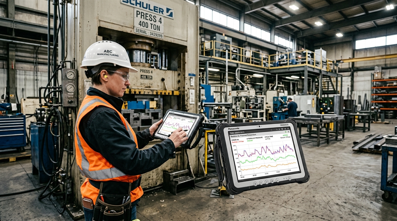
Figure 2: Real-time predictive maintenance control interface displaying multi-parameter vibration signatures, oil cleanliness indices, and automated RUL projections.
What Role Does Digital Twin Technology Play in Fluid Power Engineering?
A Digital Twin is not a static 3D CAD visualization; it is an active, physics-based mathematical replica of a physical hydraulic system that operates simultaneously in a digital simulation environment. Fed continuously by live telemetry from field sensors, the Digital Twin runs complex thermodynamic, kinematic, and fluid dynamics equations (Navier-Stokes approximations, Reynolds number calculations, and bulk modulus compressibility curves) in real time.
This dynamic co-simulation unlocks extraordinary engineering capabilities:
- Virtual Commissioning & Stress Testing: When plant engineers intend to shorten press cycle times or increase operating pressure by 15%, experimenting on the physical machine risks hose blowouts, valve spool lockups, and structural frame fatigue. The Digital Twin simulates the exact pressure spikes, oil heat generation, and cooling circuit demands in silico. It alerts engineers if heat exchanger capacity will be exceeded or if the suction line diameter must be enlarged to avert pump cavitation.
- Virtual Sensor Integration (Soft Sensing): Physical sensors cannot be installed inside every high-pressure cavity or rotating piston assembly. Digital Twin algorithms calculate unmeasured internal states—such as instantaneous oil film thickness between the cylinder rod and seal, or localized fluid temperature inside a proportional valve orifice—providing diagnostic depth impossible with hardware alone.
"In modern heavy manufacturing, the cost of an unexpected multi-hour shutdown on a primary hydraulic press vastly exceeds the entire capital outlay required to outfit the machine with smart condition sensors and edge telematics. True Industry 4.0 engineering is not about accumulating terabytes of unused telemetry; it is about interpreting the subtle thermal, vibrational, and pressure cues through which heavy machinery communicates its health."
— BRS PROSES Fluid Power & Automation Engineering Directorate
How Can Operational Technology (OT) Networks Be Secured Against Cyber Threats?
Connecting hydraulic power units and motion controllers to enterprise local area networks (LANs) and cloud analytics introduces serious cybersecurity vulnerabilities previously unfamiliar to fluid power specialists. If Operational Technology (OT) controlling physical actuators operating at 350 bar is bridged indiscriminately with office Information Technology (IT) networks, malware or unauthorized intrusion could override pressure relief setpoints, command uncontrolled cylinder movements, or trigger devastating mechanical collisions.
To ensure absolute operational safety, smart hydraulic installations engineered by BRS PROSES strictly adhere to the IEC 62443 standard for industrial automation cybersecurity:
- Physical & Logical Network Segmentation (Purdue Model): OT fieldbus networks (Level 1/2) are strictly separated from IT business systems (Level 4) via industrial hardware firewalls and Demilitarized Zones (DMZ). Broadcast traffic from corporate networks is physically incapable of reaching critical valve solenoids.
- Hardware Data Diodes: For high-security installations, diagnostic data outbound to the enterprise cloud flows through optical data diodes that physically permit transmission in one direction only. Incoming network packets cannot traverse the physical barrier, eliminating remote attack vectors.
- Encrypted Remote Maintenance Channels: When engineering support requires remote parameter adjustment, access is granted solely through IPsec/TLS 1.3 VPN tunnels utilizing hardware-enforced token authentication, Multi-Factor Authentication (MFA), and strictly bounded, time-limited access windows.
How Do Smart Servo-Pumps and Variable Frequency Drives Eliminate Energy Waste?
Beyond predictive maintenance and diagnostics, the most immediate financial return generated by smart hydraulic systems stems from energy decarbonization. Traditional hydraulic power packs employ fixed-displacement gear or axial piston pumps driven by standard AC induction motors rotating continuously at full synchronous speed (typically 1500 RPM). During dwell periods, mold clamping, or component cooling—which often comprise 40% to 70% of a machine's operating cycle—unneeded pressurized fluid is forced across pressure relief valves directly back to the reservoir. This converted hydraulic energy dissipates entirely as waste heat, which then demands additional electrical energy for cooling chillers and heat exchanger fans.
Smart variable-speed drive systems (servo-pumps and VFD-coupled axial piston units) revolutionize this dynamic. By continuously monitoring pressure transducers and actuator position encoders, the servo controller calculates the exact volumetric flow and pressure demanded by the load at each millisecond:
- Dynamic Speed Throttling: During idle holding states, motor speed drops from 1500 RPM down to 50–150 RPM, delivering just enough fluid to compensate for internal valve spool leakage while holding clamp pressure.
- Zero-Bypass Operation: Flow is governed at the pump shaft rather than through throttling valves, virtually eliminating throttling heat generation and extending hydraulic oil service life by up to 300%.
- Documented Energy Reductions: Across real-world installations in automotive press shops, plastic injection machinery, and heavy metal fabrication, smart servo-pump conversions achieve verified energy reductions between 50% and 82%, delivering full capital amortization within 8 to 18 months.
Strategic Checklist: Preparing Your Plant for Smart Hydraulic Integration
5-Step Smart Hydraulic Implementation Framework
- Baseline Assessment: Audit critical circuits for existing test port compatibility (Minimess), baseline operating pressure, fluid cleanliness class (ISO 4406), and duty cycle energy profiles.
- Sensor Architecture Selection: Specify smart IO-Link transducers for dynamic pressure, fluid dielectric quality, inline particle counts, and bearing vibration.
- Edge Computing Gateway Integration: Deploy localized edge hardware capable of embedded FFT calculation and protocol translation (IO-Link to OPC UA / MQTT).
- OT Network Hardening: Configure IEC 62443 compliant firewall rules, VLAN isolation, and encrypted remote telemetry tunnels.
- Predictive Analytics Commissioning: Establish algorithm baselines over the first 500 operating hours to train machine learning models against ambient temperature shifts and variable workload profiles.
Conclusion: The Inevitable ROI of Industrial Intelligence
In modern manufacturing, digital transformation is no longer an optional luxury or an experimental pilot project; it is the definitive benchmark of industrial competitiveness. Unplanned machine stoppages, excessive energy dissipation, and catastrophic mechanical breakdowns impose crushing costs that can compromise a company's market viability. By uniting mechanical hydraulic craftsmanship with cutting-edge digital intelligence, BRS PROSES delivers robust fluid power infrastructure engineered to meet the stringent demands of Industry 4.0.
Whether designing brand-new intelligent power units or retrofitting veteran production machinery with advanced sensory arrays, investing in smart hydraulic architecture yields immediate operational transparency, verifiable energy reductions, and total confidence in manufacturing continuity.