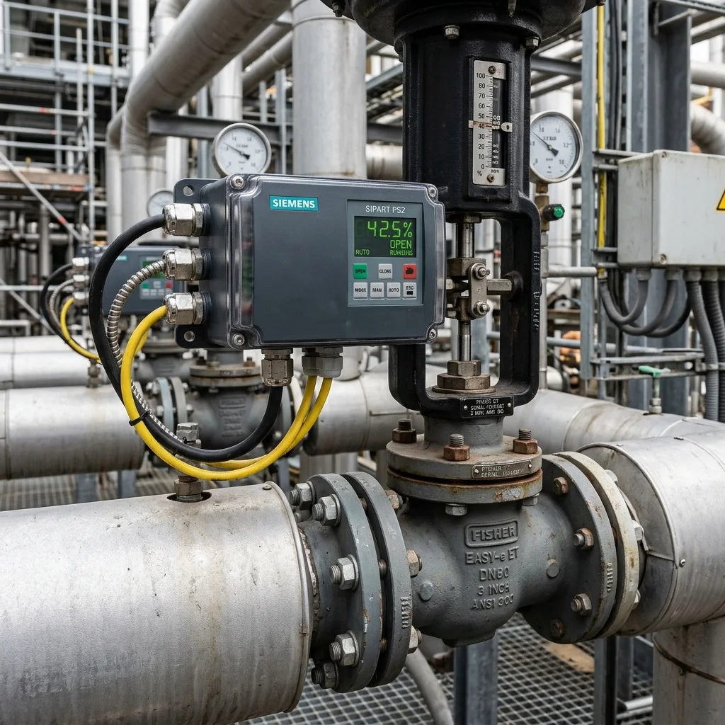
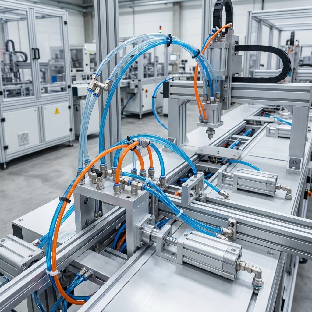
A proportional valve isn't just a component - it's the bridge that makes a system automatic and precise, turning an electronic signal into mechanical motion, and that motion into controllable flow.
1. What Is a Proportional Valve
A proportional valve gradually changes its opening in proportion to an incoming electrical signal. Unlike a classic on/off valve, it can move through infinite intermediate positions, enabling precise flow or pressure adjustment.
2. Application Areas
| Sector | Application | Proportional Valve's Role |
|---|
| Plastic Injection | Mold filling | Real-time tracking of speed/pressure profile |
| Test Rigs | Fatigue testing | Programming dynamic force profile via software |
| Dosing Lines | Liquid/powder filling | Gradual push-speed adjustment |
| Textile Machines | Yarn tension | Constant tension control |
- Plastic Injection Machines: injection speed and pressure differ at every stage of mold filling; a fixed valve can't provide this precision
- Test Rigs: when a load must follow a specific curve, software programming replaces a mechanical cam
- Dosing Lines: push speed of liquid/powder is adjusted gradually, directly affecting fill precision
"The precision a proportional valve offers is only meaningful when paired with proper sensor feedback and a control card of sufficient resolution."
— BRS PROSES Engineering Team
3. BRS Proses Application Support
- Application-specific valve and control architecture design
- Sensor feedback integration
- PLC/control card resolution compatibility check
- Field commissioning and calibration
6. Frequency Response & Spool Resonant Frequency Bandwidth
In dynamic hydroforming, tube bending, and high-frequency fatigue test machines, selecting a proportional valve solely based on nominal flow ($Q_N$) leads to phase lag and system instability. Control engineers must evaluate the valve’s frequency response bandwidth, defined at the $-3 ext{dB}$ amplitude attenuation or $-90^circ$ phase shift threshold:
- Standard Proportional Spool Valves ($f_{-3dB} approx 10–20 ext{Hz}$): Suitable for basic speed ramping, transfer carriages, and soft deceleration.
- High-Dynamic Servo-Proportional Valves ($f_{-3dB} ge 70–100 ext{Hz}$): Equipped with high-force voice coil linear drives, micro-machined zero overlap spools, and onboard digital DSP electronics. Capable of executing high-cadence closed-loop position and pressure loops with sub-millisecond response.
7. Multi-Axis Electronic Synchronization in Heavy Hydraulic Presses
In wide platen hydraulic presses (e.g., 2,500 mm bed width driven by dual main cylinders), uneven workpiece resistance causes mechanical tilting and guide jamming. BRS PROSES achieves active electronic tilt synchronization:
| Architecture Level |
Hardware & Transducer Setup |
Controller Synchronization Precision |
| Master-Slave Synchronization |
Dual optical linear scales (1 μm) + Slave follows Master |
±0.10 mm (Subject to dynamic lag) |
| Cross-Coupled Electronic Axis Loop |
Synchronous real-time DSP evaluating platen parallel error |
±0.02 mm under 150-ton eccentric load |
| p/Q Combined Control Mode |
Integrated dual-chamber pressure sensors + position scale |
Seamless bumpless switch between speed and force limit |
Closed-Loop Control Architecture: LVDT Spool Feedback, Dither & Ramp Calibration
In high-precision hydraulic motions, traditional open-loop directional control valves cannot guarantee smooth deceleration or micron-level repeatability due to flow forces and fluid friction. Proportional valves with integrated electronics (OBE - On-Board Electronics) solve this through closed-loop spool position control using inductive Linear Variable Differential Transformers (LVDT).
1. Overcoming Spool Stiction via High-Frequency Dither
Static friction (stiction) between the ground valve spool and sleeve induces hysteresis (lag between command signal and fluid flow). Digital amplifier cards superimpose a small, high-frequency AC dither signal (typically 100 Hz to 250 Hz, with 2%–5% amplitude) onto the main DC command current. This keeps the spool in constant microscopic oscillation, transforming static friction into dynamic sliding friction and slashing system hysteresis to under 0.5%.
2. Electronic Ramp Generator Functionality
Sudden spool shifts create hydraulic shock waves ("water hammer") exceeding 250% of nominal pressure, damaging transducers and hose fittings. Electronic ramp functions enforce controlled acceleration and deceleration curves (adjustable from 0.05 s to 10.0 s), cushioning heavy inertia masses in hydraulic press rams, injection moulding clamps, and turbine governor actuators.
Technical Field Inspection & Commissioning Protocol
Prior to signing off on any fluid power retrofit, system upgrade, or routine component overhaul, technical commissioning engineers must rigorously complete the following verification procedures to ensure full compliance with ISO machinery safety standards:
- Static Hydrostatic / Pneumatic Pressure Proof Test: Pressurize circuit to 1.5× maximum design working pressure for 15 minutes, inspecting all welded flanges and fittings for micro-weeping.
- Contamination & Fluid Particle Verification: Draw dynamic fluid samples under working temperature and confirm ISO 4406 cleanliness classes (or ISO 8573-1 air dew point classes) before activating sensitive proportional spool valves.
- Thermal Baseline Profiling: Record continuous thermal infrared scans of pump casings, valve manifold manifolds, and accumulator bodies across 4 hours of full-load production cycles to confirm proper thermal dissipation.
- Failsafe & Emergency De-energization: Verify manual LOTO isolation valves, dump valves, and accumulator vent blocks discharge trapped hydraulic/pneumatic kinetic energy to 0 bar within 2.0 seconds of emergency e-stop triggering.