Rising energy costs have made hydraulic system efficiency a necessity rather than a
choice.
A
correctly optimized hydraulic system not only lowers energy bills but
also
extends component life, reduces failures, and shrinks your carbon footprint.
Striking Statistic
Approximately 15-20% of total energy consumption in
industrial facilities comes from hydraulic and pneumatic systems. It is possible to
achieve
up to 30% savings with efficiency-focused modernization.
1. Key Factors Reducing Efficiency
There can be many reasons for a system's inefficient operation. Energy loss usually
turns
into
heat, which increases the cooling load of the system, creating a "double damage".
1.1. Over-sizing
Electric motors and pumps chosen larger than necessary with "just in case" logic always
operate
below the optimum efficiency point. This unnecessarily increases both the initial
investment
cost and operating expenses.
| Source of Inefficiency
|
Problem Caused |
Suggested Solution |
| Internal
Leaks
|
Volumetric
efficiency
loss, heating |
Seal/gasket
replacement,
worn valve repair |
| Incorrect
Pipe
Diameter
|
High pressure
drop (ΔP)
|
Large
diameter
piping
suitable for flow rate |
| Dirty Filters
|
Pump
cavitation,
flow
resistance |
Regular
filter
replacement and monitoring |
| Incorrect Oil Selection |
Friction losses or leakage |
Viscosity selection suitable for operating
temperature |
2. Transformation with Modern Technologies
Transitioning from traditional fixed displacement systems to modern technologies can
shorten
the
return on investment (ROI) surprisingly.
2.1. Load Sensing Systems
Load sensing pumps produce only the flow and pressure the system needs. In standby
states
where
there is no load, energy consumption drops to almost zero.
2.2. Variable Frequency Drives (VFD)
Inverter systems that adjust the speed of the electric motor according to hydraulic
demand
are the
pinnacle of energy saving. Motor speed idling at fixed speed is becoming history.
"Efficiency is not a one-time adjustment, but a continuous process. Even the most
modern
system
— BRS PROSES Engineering Team
3. Heat Management: The Hidden Energy Thief
Heat = Lost Energy
If your hydraulic system is operating above 60°C,
something is
wrong. Excessive heat is the most concrete evidence of lost energy spent in the
system
but not
converted into work.
Heating problems usually stem from either insufficient cooling capacity or (more often)
unnecessary pressure drops in the system. As BRS PROSES, we detect "hot
spots" in
your system with thermal camera analysis and eliminate the source of inefficiency at the
point.
4. Energy Audit with BRS PROSES
We offer a professional roadmap to increase your business's energy
efficiency:
- Current system flow, pressure
and
power analysis
- Leak
detection with thermal imaging
- Revision cost and amortization
(ROI) calculation
- On-site modernization and
commissioning
- Personnel training
6. Direct-Acting vs. Pilot-Operated Pressure Relief Dynamics
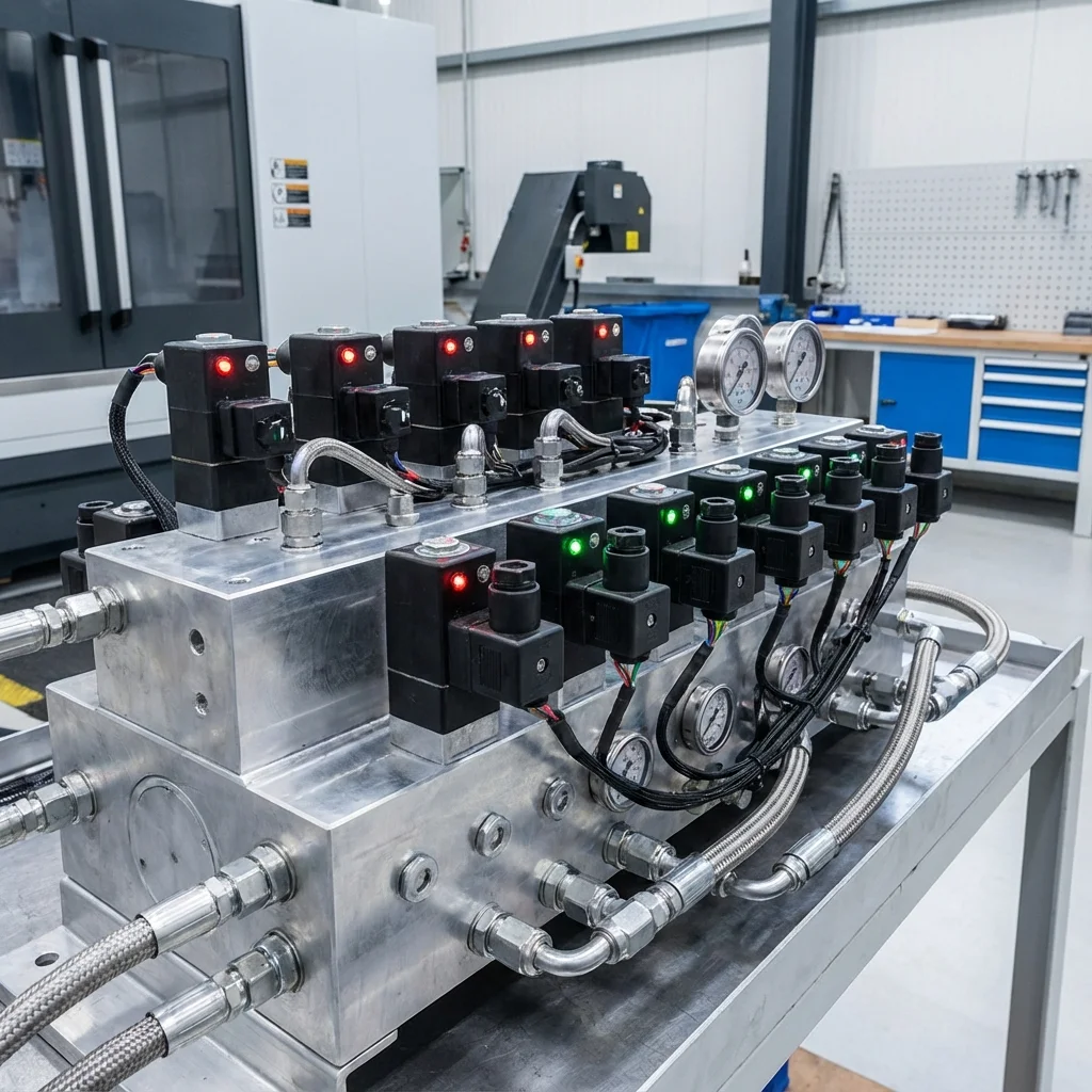
Pressure relief valves protect hydraulic circuits from catastrophic overpressurization. Understanding the dynamic distinction between direct-acting and two-stage pilot-operated topologies dictates circuit stability:
- Direct-Acting Poppet Relief: High cracking speed (reaction time 2 to 6 ms) makes them ideal for absorbing explosive pressure spikes. However, they exhibit significant pressure override ($Delta P_{ ext{override}} = P_{ ext{full flow}} - P_{ ext{cracking}} approx 20–35 ext{bar}$), resulting in poor energy efficiency at high flows.
- Pilot-Operated Spool Relief: Features an integrated pilot stage that balances main spool pressure. Extremely flat $P–Q$ characteristic ($Delta P_{ ext{override}} < 5 ext{bar}$), ensuring system pressure remains constant across varying flow rates. Response time is slightly slower (15 to 30 ms), making a hybrid direct-acting shock cushion valve recommended for high-dynamic circuits.
7. Counterbalance & Load-Holding Safety Architecture
In applications supporting suspended overrunning loads (crane winches, vertical press platens), counterbalance valves prevent runaway descent. Pilot ratios (typically 3:1, 4.5:1, or 8:1) balance load-holding security against hydraulic energy loss:
| Pilot Ratio |
Stability Profile |
Pilot Pressure Required |
Recommended System Dynamics |
| 3:1 Low Ratio |
Ultra-Stable / No chatter |
High pilot pressure needed |
Long boom cranes, compliant structures subject to bounce |
| 4.5:1 Standard Ratio |
Balanced stability & efficiency |
Moderate pilot pressure |
General industrial cylinders, vertical hydraulic presses |
| 8:1 – 10:1 High Ratio |
Fast response / Sensitive |
Very low pilot pressure |
Rigid machine beds, constant-load motor drive winches |
Pressure Valve Dynamics: Direct-Operated vs Pilot-Operated Stability & Override Curves
Pressure control valves regulate system safety, sequential actuation, and load holding across complex industrial hydraulic networks. Specifying between direct-acting poppet valves and two-stage pilot-operated cartridge valves requires evaluating pressure override curves and dynamic stability under rapid flow transients.
1. Pressure Override Comparison & Flow Characteristics
Direct-Operated Relief Valves: Feature rapid response times (2 to 5 milliseconds), making them ideal for clipping instantaneous shock spikes. However, they exhibit a large pressure override ((Delta P)), meaning the pressure required to pass full rated flow can be 20% to 35% higher than initial cracking pressure.
Pilot-Operated Relief Valves: Use a small pilot poppet to control the unbalance across a balanced main spool. They deliver a nearly flat pressure-flow curve (override < 5%), maintaining steady working pressure from low leakage flows up to 600 L/min, though response times range from 15 to 30 ms.
2. Counterbalance (Load-Holding) Valve Pilot Ratio Sizing
Counterbalance valves prevent suspended loads (e.g. crane booms, vertical press rams) from falling uncontrollably. Setting the pilot ratio (typically 3:1, 4.5:1, or 10:1) dictates the pilot pressure needed to open the valve against the load-induced pressure. Lower pilot ratios (3:1) provide superior stability and prevent chattering on bouncy loads, whereas higher ratios (10:1) minimize energy consumption during lowering cycles.