In a pneumatic system, the component actually moving the cylinder isn't the compressor - it's the directional control valve. Pick the wrong type and the system either costs more than it needs to or fails to do the job.
| Valve Type | Ports/Positions | Typical Use |
|---|
| 3/2 Valve | 3 ports / 2 positions | Single-acting cylinder |
| 5/2 Valve | 5 ports / 2 positions | Double-acting cylinder (standard) |
| 5/3 Valve (closed center) | 5 ports / 3 positions | Mid-stroke stop |
| 5/3 Valve (open center) | 5 ports / 3 positions | Vent both sides on emergency stop |
1. Valves by Port and Position Count
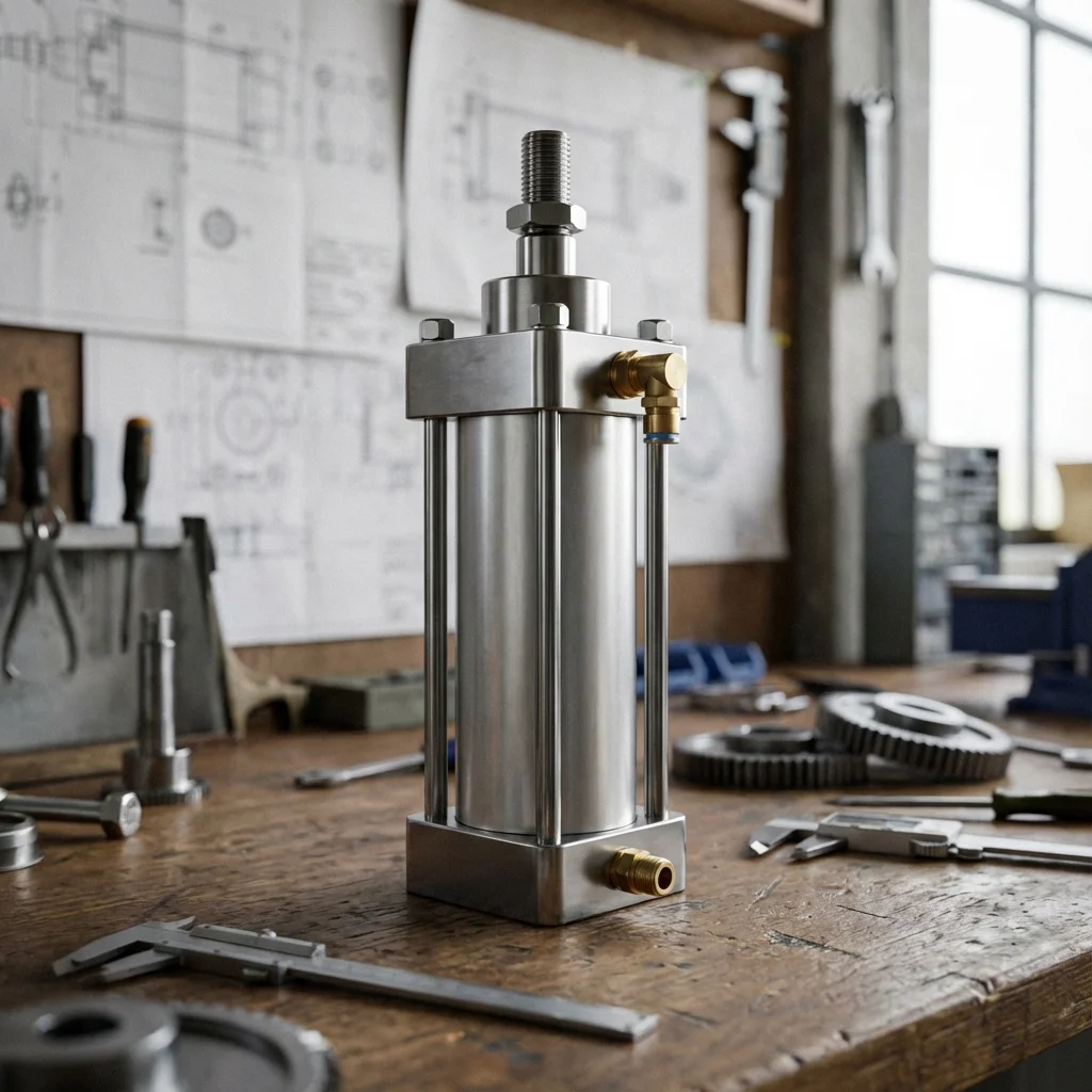
A 3/2 valve is enough to drive a single-acting cylinder. Double-acting cylinders standardly use a 5/2 valve, since it manages separate air paths for both forward and return motion.
1.1. The Special Case of the 5/3 Valve
A 5/3 valve has an extra middle "closed center" or "open center" position, allowing the cylinder to stop mid-stroke or vent both sides to atmosphere when power is cut - preferred in safety stop applications.
2. Actuation Method
- Mechanical/Manual: operated by button, pedal, or roller lever; suited to electricity-free applications
- Solenoid (Single Coil): runs on PLC signal, returns to prior position via spring
- Solenoid (Double Coil): switches with a coil signal at both positions, holds last position even if power is cut
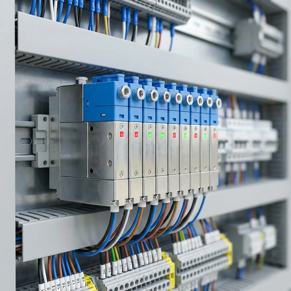
"Valve terminals connect multiple valves to a single air supply and a single electrical connector, cutting installation time roughly in half."
— BRS PROSES Engineering Team
3. BRS Proses Valve Selection Support
- Valve configuration recommendation based on cylinder type
- Valve terminal (manifold) design
- PLC integration consulting
- Fast valve diagnostics on failure
6. Spool Architecture vs. Poppet Valve Mechanics
The fundamental internal valving element governs whether a pneumatic directional valve can tolerate contaminated factory air or deliver zero internal leakage:
- Axial Spool Design: Features a precision ground aluminum or stainless spool sliding inside an elastomeric seal sleeve. Permits multi-position configurations (5/3 closed center, exhausted center, pressurized center) with balanced static actuation forces. However, seal friction and particulate abrasion can cause micro-leakage over tens of millions of cycles.
- Poppet Seat Design: Features spring-loaded discs or balls closing against flat vulcanized rubber seats. Delivers absolute zero internal leakage (bubble-tight shutoff) and inherently self-cleans against dust or compressor varnishing. Restricted primarily to 2/2, 3/2, and dual 3/2 functional topologies.
7. Standardized Mounting Interfaces: ISO 5599-1, ISO 15407 & NAMUR
To prevent proprietary vendor lock-in and minimize machine downtime, BRS PROSES adheres strictly to international valve sub-base standards:
| Mounting Standard |
Size Classifications |
Nominal Flow Range ($Q_N$) |
Standard Industry Application |
| ISO 5599-1 |
Sizes 1, 2, 3, 4 (Sub-base) |
1,200 to 6,000 Nl/min |
Heavy automotive stamping, tire presses, foundry jigs |
| ISO 15407-1 / -2 |
18 mm and 26 mm modular width |
400 to 1,200 Nl/min |
Packaging machines, electronics pick-and-place, robotics |
| VDI/VDE 3845 (NAMUR) |
Direct mount to rotary actuator pinions |
700 to 1,500 Nl/min |
Process automation: butterfly valves, ball valve actuation |
Valve Sizing Dynamics: Sonic Conductance (C), Critical Pressure Ratio (b) & Flow (Qn)
Selecting pneumatic directional control valves by port thread size (e.g., G 1/4" or G 1/2") is a widespread engineering error. Port threading does not dictate internal flow capacity. Under ISO 6358, valve flow capacities are mathematically defined by two universal pneumatic parameters: Sonic Conductance ((C)) and Critical Pressure Ratio ((b)).
1. Choked vs Subsonic Compressible Flow Dynamics
When the downstream pressure ratio ((P_2 + 1) / (P_1 + 1) le b), the air velocity within the valve orifice reaches sonic speed (Mach 1). At this choked state, increasing the pressure differential across the valve cannot increase mass flow rate. The nominal flow rate (Qn) (Nl/min at inlet 6 bar, (Delta P = 1 ext{ bar})) must be calculated to match peak cylinder stroke velocities:
Q_req = (A_cyl × v_max × P_sys) / 1000 (Nl/min)
If the valve nominal flow (Qn) is lower than (Q_{req}), the cylinder will experience sluggish start-up acceleration and erratic deceleration.
2. Spool Valve vs Poppet Valve Response Times
- Spool Architecture: Provides balanced axial forces and versatile multi-port configurations (5/2, 5/3 Center Closed / Exhausted). Switching time: 15–35 ms.
- Poppet Architecture: Employs flat elastomeric face discs against metallic valve seats. Provides zero-leakage sealing, self-cleaning seats, and ultra-rapid response times (5–12 ms), making poppet valves the premier choice for emergency dump circuits.
Technical Field Inspection & Commissioning Protocol
Prior to signing off on any fluid power retrofit, system upgrade, or routine component overhaul, technical commissioning engineers must rigorously complete the following verification procedures to ensure full compliance with ISO machinery safety standards:
- Static Hydrostatic / Pneumatic Pressure Proof Test: Pressurize circuit to 1.5× maximum design working pressure for 15 minutes, inspecting all welded flanges and fittings for micro-weeping.
- Contamination & Fluid Particle Verification: Draw dynamic fluid samples under working temperature and confirm ISO 4406 cleanliness classes (or ISO 8573-1 air dew point classes) before activating sensitive proportional spool valves.
- Thermal Baseline Profiling: Record continuous thermal infrared scans of pump casings, valve manifold manifolds, and accumulator bodies across 4 hours of full-load production cycles to confirm proper thermal dissipation.
- Failsafe & Emergency De-energization: Verify manual LOTO isolation valves, dump valves, and accumulator vent blocks discharge trapped hydraulic/pneumatic kinetic energy to 0 bar within 2.0 seconds of emergency e-stop triggering.