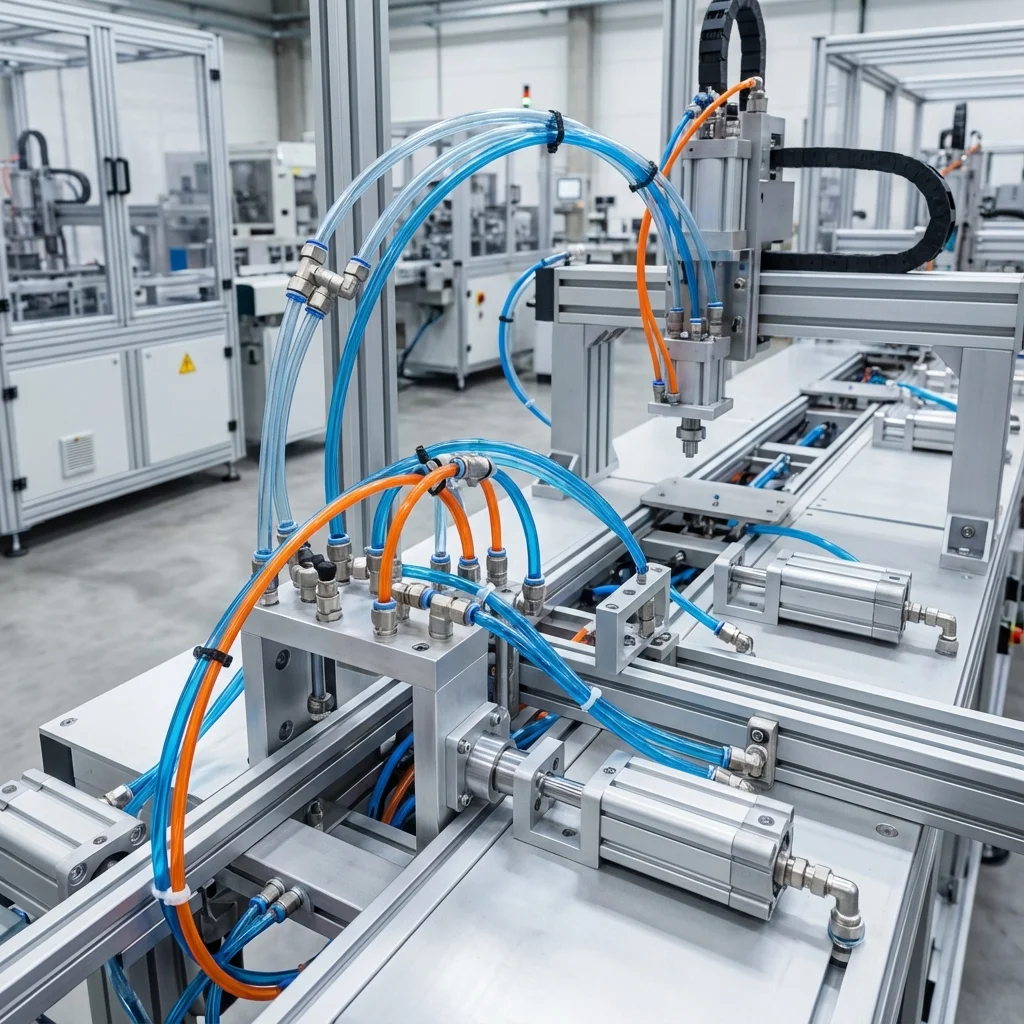
Compressed air is one of the most expensive energy forms on a production line - but a well-designed pneumatic system pays that cost back many times over with its speed and simplicity.
1. Core Components
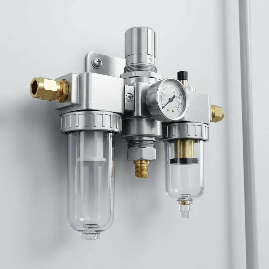
A pneumatic system's backbone is four components: compressor, air preparation unit (FRL), directional control valves, and cylinders.
- Compressor: the system's air source, sized to flow and pressure needs
- FRL Unit: cleans the air, stabilizes pressure, lubricates if needed
- Directional Control Valves: route air to the right path at the right time
- Cylinders: convert force into motion; larger bore means more force but less speed
Industry 4.0 Integration
Units equipped with pressure and position sensors can flag even a 10% lengthening of cycle time before a planned-maintenance trigger would.
2. Common Application Areas
| Sector/Line | Typical Use | Priority |
|---|
| Packaging Lines | Fast push-pull motion | Speed |
| Assembly Stations | Part clamping | Repeatability |
| Automotive Paint Booths | Door open-close mechanism | Cleanliness/hygiene |
"When designing a new pneumatic line, air consumption is calculated first, then the compressor and line diameter are sized accordingly; reversing that order is the most common design mistake in the field."
— BRS PROSES Engineering Team
3. BRS Proses System Design Support
- Line design starting from the air budget
- Compressor and FRL sizing
- Industry 4.0 sensor integration consulting
- Turnkey pneumatic line installation
6. Piezoelectric Bending Actuator Valving & PWM Flow Modulation
Traditional pneumatic solenoid valves generate electromagnetic actuation forces via copper coils, consuming continuous holding current and suffering thermal heating that shifts valve response characteristics.
Next-generation pneumatic technologies deploy piezoelectric ceramic bending benders. Piezo valves operate capacitively: they draw zero electrical holding power once charged, generate zero thermal heat dissipation, and switch in less than 1 to 2 milliseconds. By combining piezo benders with high-frequency Pulse-Width Modulation (PWM), digital pneumatic controllers achieve continuous flow regulation without mechanical spool friction or hysteresis.
7. Cyber-Physical Pneumatics: Edge Diagnostics & Wireless IO-Link
The integration of miniature MEMS pressure and flow sensors directly inside pneumatic valve terminal slices enables self-diagnosing fluidic systems:
| Smart Pneumatic Feature |
Embedded Sensor Technology |
Autonomous Factory Value |
| Autonomous Leak Detection |
Delta-pressure hold sensing during machine stop |
Alerts maintenance to localized seal degradation before line failure |
| Dynamic Pressure Economizing |
Dual-pressure chamber control via software recipes |
Reduces return-stroke air consumption by up to 40% |
| Wireless IO-Link Fieldbus |
2.4 GHz industrial wireless node integration |
Permits installation on rotary index tables without slip-ring wear |
Next-Generation Smart Pneumatics: IO-Link, Edge Analytics & Predictive Maintenance
Traditional pneumatics relied purely on on/off solenoid valves and magnetic reed switches. Modern automation infrastructure demands continuous operational telemetry to eliminate unexpected downtime and minimize power consumption. Smart pneumatic ecosystems now embed micro-electromechanical sensors (MEMS) directly into valve manifolds, pressure regulators, and cylinder bodies.
1. IO-Link Integration & Real-Time Sensor Telemetry
IO-Link (IEC 61131-9) enables point-to-point bidirectional digital communication over unshielded 3-wire standard cables. By connecting smart pneumatic valve islands to IO-Link Master modules, machine PLCs receive real-time operational parameters:
- Actuator Cycle Velocity: Continuous measurement of stroke duration in milliseconds to detect mechanical friction or seal wear before jamming occurs.
- Differential Pressure Drops: Tracking pressure gradients across FRL filter elements to automatically notify technicians when micron cartridges require replacement.
- Coil Cycle Counters & Remaining Useful Life (RUL): Real-time logging of valve actuations against certified 50-million cycle lifespans to trigger scheduled component swaps.
2. Digital Flow Rate Monitoring & Automatic Leak Mitigation
Smart air supply modules continuously analyze mass flow rate (Nl/min). During standby periods or weekend shutdowns, if baseline flow exceeds a pre-set threshold (e.g. > 15 Nl/min), an integrated pilot valve automatically isolates that branch of the machine, preventing compressor run-hours and saving thousands of Euros in electrical energy annually.
Technical Field Inspection & Commissioning Protocol
Prior to signing off on any fluid power retrofit, system upgrade, or routine component overhaul, technical commissioning engineers must rigorously complete the following verification procedures to ensure full compliance with ISO machinery safety standards:
- Static Hydrostatic / Pneumatic Pressure Proof Test: Pressurize circuit to 1.5× maximum design working pressure for 15 minutes, inspecting all welded flanges and fittings for micro-weeping.
- Contamination & Fluid Particle Verification: Draw dynamic fluid samples under working temperature and confirm ISO 4406 cleanliness classes (or ISO 8573-1 air dew point classes) before activating sensitive proportional spool valves.
- Thermal Baseline Profiling: Record continuous thermal infrared scans of pump casings, valve manifold manifolds, and accumulator bodies across 4 hours of full-load production cycles to confirm proper thermal dissipation.
- Failsafe & Emergency De-energization: Verify manual LOTO isolation valves, dump valves, and accumulator vent blocks discharge trapped hydraulic/pneumatic kinetic energy to 0 bar within 2.0 seconds of emergency e-stop triggering.