For decades, a persistent design dogma has dominated the industrial automation sector: pneumatic systems excel at speed, durability, and raw cost-efficiency, but are fundamentally unsuitable when multi-point intermediate positioning requires sub-millimeter or micron-level precision. In traditional open-loop pneumatic circuits driven by discrete on-off solenoid valves, this skepticism was mathematically justified. However, the convergence of micro-machined proportional spool valves, ultra-fast magnetostrictive linear transducers, and 32-bit digital state-space DSP controllers has completely rewritten these technical boundaries. Today, servo-pneumatics delivers programmable intermediate positioning, dynamic acceleration shaping, and active force regulation with repeatable tolerances between ±0.05 mm and ±0.1 mm. In this engineering monograph, we dissect the thermodynamic constraints of air compressibility, explore closed-loop hardware topologies, analyze kinetic energy dissipation, and outline BRS PROSES’ proprietary design framework for high-precision pneumatic actuation.
Executive Summary: The Modern Servo-Pneumatic Mandate
Precise pneumatic positioning does not fight air elasticity—it models and harnesses it. By coordinating dual-port pressure feedback with real-time positional updates at ≥1 kHz cycle rates, servo-pneumatics combines the inherent compliance and high power-to-weight ratio of fluid power with the programmable multi-stop flexibility traditionally monopolized by electromechanical ball screws.
1. Thermodynamics of Air Compressibility: Compliant Spring vs. Dynamic Stiffness
Unlike mineral hydraulic oils, which exhibit a bulk modulus of approximately 1.5 to 2.0 GPa (practically incompressible for standard automation envelopes), compressed air is an elastic gas governed by the ideal gas law and polytropic thermodynamic transformations:
P · Vn = ext{constant} quad ext{where } 1.0 < n ≤ 1.4 quad ( ext{Isothermal to Isentropic})
When a pneumatic cylinder moves, the gas volumes in both the cap-end chamber ($V_1$) and rod-end chamber ($V_2$) change dynamically. The effective pneumatic stiffness ($k_{ ext{air}}$) of the double-acting actuator is not constant; it depends directly on operating gauge pressure, piston surface areas ($A_1, A_2$), and instantaneous stroke position ($x$):
k_{ ext{air}}(x) = gamma left[ �rac{P_1(x) cdot A_1^2}{V_1(x)} + �rac{P_2(x) cdot A_2^2}{V_2(x)}
ight] quad [N/m]
This non-linear pneumatic stiffness causes the natural resonance frequency ($omega_n = sqrt{k_{ ext{air}} / M}$) of the moving mass ($M$) to reach its lowest, most unstable point near the center of the cylinder stroke. In open-loop circuits, external cutting forces, gravitational vectors, or inertial surges cause the piston to bounce or oscillate erratically around target coordinates.
Furthermore, friction phenomena dictated by the Stribeck curve—where static breakaway friction ($mu_s$) is substantially higher than dynamic Coulomb friction ($mu_k$)—introduce severe "stick-slip" behavior. When attempting to micro-step an open-loop cylinder by brief valve pulsing, pressure must build up behind the elastomeric seal until it overcomes $mu_s$. The instant movement begins, resistance drops sharply, causing the cylinder to jerk forward and dramatically overshoot its command position. Eliminating this requires closed-loop active damping where proportional valves pressurize both opposing chambers simultaneously to create dynamic pneumatic clamping.
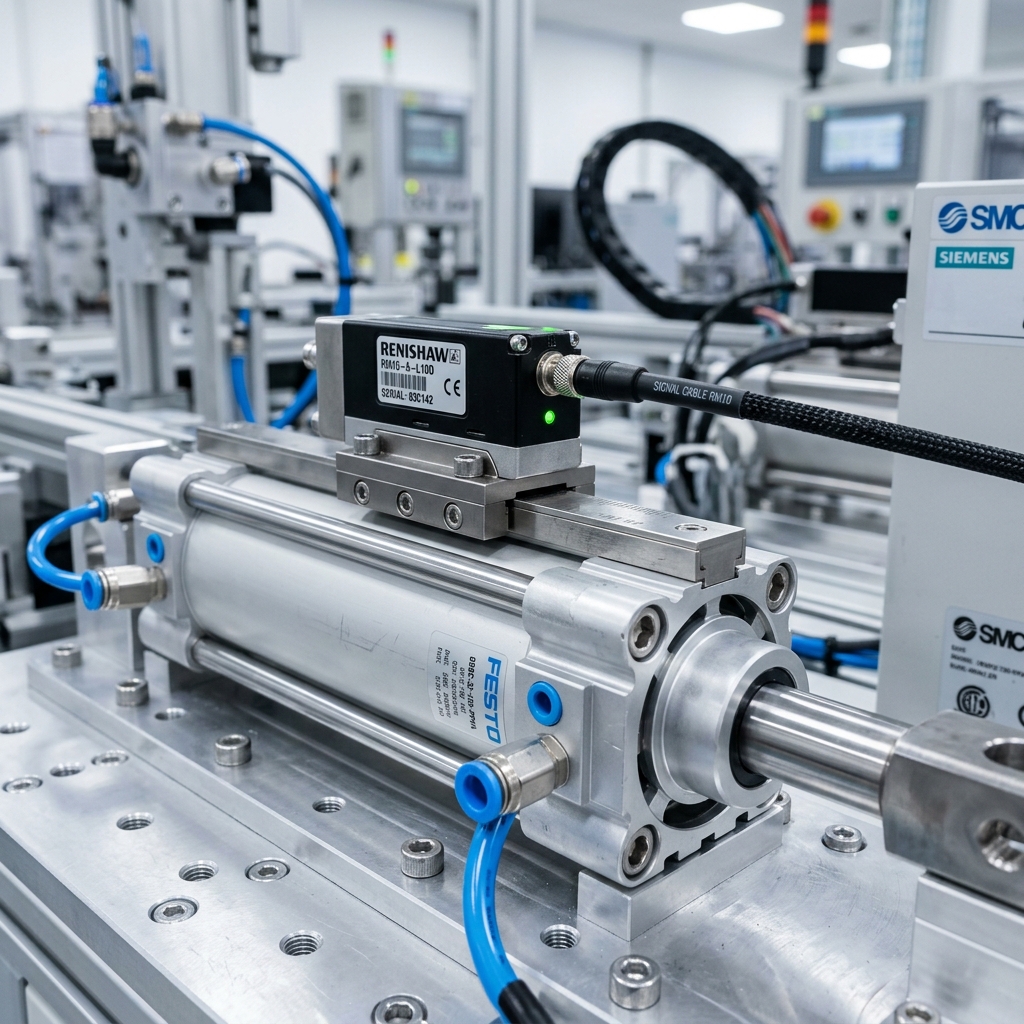
Industrial high-precision aluminum pneumatic actuator integrated with high-resolution magnetic linear displacement encoder.
2. Core Hardware Pillars of Precision Servo-Pneumatic Architectures
Achieving dependable, high-speed positioning within ±0.05 mm requires a balanced tripartite hardware system encompassing rapid valve actuation, sub-micron positional metrology, and stiff mechanical guidance.
2.1. 5/3 Proportional Directional Flow & Pressure Servo Valves
Standard industrial 5/2 or 5/3 solenoid directional valves utilize digital on/off armatures with shifting response times between 20 ms and 60 ms. This latency is far too sluggish for closed-loop stability. In contrast, servo-pneumatic systems employ specialized 5/3 proportional directional control valves equipped with linear voice-coil drives or high-force proportional solenoids:
- High Cutoff Frequency (>80 Hz – 120 Hz): Spool repositioning occurs in less than 5 to 8 milliseconds, permitting real-time correction of transient load disturbances.
- Zero Overlap (Critical Center Spool): Standard directional valves feature 10% to 20% positive spool overlap to prevent center leakage, creating a massive deadband. Servo spools are micro-machined with zero overlap (±0.5%), ensuring immediate volumetric flow change upon the slightest control voltage deviation (±10 mV).
- Integrated Spool LVDT Feedback: An internal Linear Variable Differential Transformer (LVDT) continuously measures the physical spool coordinate, closing an internal minor loop that eliminates magnetic hysteresis to under 0.2%.
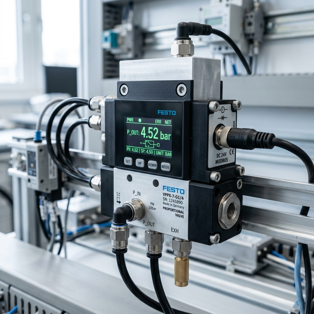
High-dynamic 5/3 proportional directional valve offering continuous mass-flow modulation.

Robotic end-of-arm tooling requiring delicate force modulation alongside exact positioning.
2.2. Linear Feedback Transducer Technologies
A control loop can only control what it can measure. The selection of the feedback sensor dictates the theoretical resolution, electrical noise immunity, and environmental survivability of the entire automation cell:
- Magnetostrictive Linear Transducers: Utilizes the Wiedemann effect, measuring the time of flight of an acoustic torsional pulse induced by a moving magnetic cursor along a ferromagnetic waveguide. Absolutely non-contact, wear-free, immune to ambient shop-floor vibrations, and hermetically sealed to IP67/IP69K. Output resolutions reach ≤1 µm via synchronous SSI or IO-Link protocols. Ideal for heavy stamping, die casting, and washdown environments.
- Magnetic & Optical Encoders: Reading tape or glass scale configurations mounted parallel to linear recirculating ball bearing guide rails. Capable of sub-micron resolution (up to 0.1 µm) and high interpolation speeds, but optical variants remain vulnerable to oil mists, condensation, and airborne particulate contamination.
- Conductive Plastic Potentiometers: Cost-effective analog transducers (0–10V) suitable for moderate stroke applications (±0.2 mm accuracy). However, physical wiper contact causes progressive resistive wear, rendering them unsuitable for high-frequency micro-dithering loops exceeding 10 million cycles.
3. Comprehensive Engineering Comparison: Linear Positioning Methodologies
Automation engineers frequently face the dilemma of choosing between mechanical hard stops, open-loop proportional setups, full servo-pneumatics, and electromechanical servo ball screws. The following technical decision matrix compares these systems across fundamental industrial parameters:
| Positioning Methodology |
Repeatability |
Multi-Stop Flexibility |
Velocity Profiling |
Power-to-Weight Ratio |
Relative Capital Cost |
| Mechanical End Stops + Shock Absorbers |
±0.05 mm (End positions only) |
Zero (Fixed 2 points) |
None (Bang-bang) |
Very High (>2.5 kW/kg) |
Low (1.0x Baseline) |
| Open-Loop Proportional Metering |
±1.0 mm – ±2.5 mm |
Poor (Drifts with load/temp) |
Basic Ramp (Open-loop) |
High (>2.0 kW/kg) |
Moderate (1.8x) |
| Servo-Pneumatics (Closed-Loop PID+State) |
±0.05 mm – ±0.1 mm |
Infinite (Fully programmable) |
Full S-Curve / Jerk Control |
Very High (>2.2 kW/kg) |
Medium (2.5x – 3.0x) |
| Electric Ball Screw Servo Actuator |
±0.005 mm – ±0.01 mm |
Infinite (Fully programmable) |
Full Advanced Profiling |
Low to Moderate (<0.8 kW/kg) |
Very High (5.0x – 7.0x) |
4. Motion Profiling, Kinetic Energy Dissipation and Mechanical Rod Clamping
A moving pneumatic mass possesses kinetic energy ($E_k = �rac{1}{2} M v^2$). When decelerating a 40 kg tooling carriage traveling at 1.2 m/s, over 28.8 Joules of energy must be dissipated in a fraction of a second. If deceleration relies solely on mechanical bottoming against cylinder endcaps, the impact force exceeds equipment yield thresholds and introduces structural shock waves throughout the machine chassis.
Precision positioning circumvents this through mathematically synthesized velocity profiles generated by the motion controller:
- S-Curve (7-Segment Jerk-Limited) Profiling: Rather than applying trapezoidal velocity steps which impart instantaneous infinite acceleration derivatives (jerk $j = �rac{da}{dt} = infty$), the controller smooths acceleration continuously. This prevents the pneumatic air column from oscillating like an underdamped spring during the braking transition.
- Active Differential Pressure Counter-Braking: During the final 15% of the stroke approaching target coordinates, the servo valve actively pressurizes the opposing cylinder chamber while simultaneously throttling exhaust flow. This creates a virtual pneumatic buffer that smoothly brings velocity to absolute zero exactly at the target point.
- Pneumatic Rod Lock Units (Failsafe Mechanical Clamping): Once the cylinder achieves zero-speed position within the ±0.05 mm window, external cutting forces or continuous air micro-leakage could induce positional drift. A spring-applied, pneumatically released mechanical rod clamping cartridge (Rod Lock) engages the hard-chrome piston rod. The clamp maintains infinite holding stiffness up to 12,000 N without consuming compressed air or relying on continuous valve modulation.
“Sub-millimeter precision in pneumatic actuation is never the triumph of an expensive transducer alone. It is an orchestrated symphony combining zero-overlap proportional valve response, deterministic high-speed control cycles, clean fluid conditioning, and rigid mechanical linear guidance.”
— BRS PROSES Automation & Motion Control Engineering Group
5. The Overlooked Variable: Thermal Dynamics and Environmental Disturbances
In high-duty industrial production, ambient temperature variations and fluid friction can degrade pneumatic positioning accuracy if left uncompensated. Based on the universal gas equation ($P =
ho R T$), an ambient temperature shift from 18°C during morning startup to 38°C in mid-afternoon alters air density ($
ho$) by nearly 7%. This changes the sonic conductance ($C$) and critical pressure ratio ($b$) of valve flow orifices (ISO 6358), causing open-loop cylinders to undershoot or overshoot their programmed destinations.
Moreover, structural differential thermal expansion introduces physical dimensional drift. An aluminum cylinder barrel expands at $alpha_{ ext{Al}} approx 23 imes 10^{-6}/ ext{K}$, while a steel piston rod and linear machine bed expand at $alpha_{ ext{Steel}} approx 11.5 imes 10^{-6}/ ext{K}$. Over a 1,000 mm stroke length and a 25°C thermal delta, differential expansion exceeds 0.28 mm—tripling an allowable ±0.1 mm tolerance envelope! In advanced BRS PROSES designs, feedback transducers are referenced directly to the rigid machine base rather than the cylinder casing, and real-time DSP temperature compensation algorithms dynamically bias target encoder counts.
6. Industrial Case Study: Automotive Stamping Press Transfer Feeder
To understand the real-world operational return of servo-pneumatics, examine an engineering project executed by BRS PROSES for a Tier-1 automotive metal stamping facility:
Case Study Specification: High-Cadence Multi-Stop Blank Feeder
- Application: High-speed sheet blank indexing across 4 discrete intermediate stamping stations.
- Moving Payload: 35 kg tooling carriage mounted on dual recirculating linear ball guides.
- Stroke & Velocity Requirements: 1,400 mm total stroke, peak velocity 1.5 m/s, cycle time ≤ 1.2 seconds.
- Target Repeatability: ±0.08 mm at all 4 intermediate work positions.
The BRS PROSES Engineered Solution:
Rather than installing an oversized, cost-prohibitive linear servo motor exposed to metal stamping dust and lube mists, BRS PROSES engineered a rodless magnetic-coupled pneumatic cylinder (Ø50 mm bore) driven by a 5/3 proportional servo valve directly mounted to the cylinder ports via rigid aluminum manifolds. An IP67 magnetostrictive linear transducer provided continuous 24-bit SSI position feedback into a dedicated motion controller running a dual-loop PID algorithm with acceleration feedforward and active chamber pressure monitoring.
Quantified Results & ROI:
- Positioning Repeatability: Measured at ±0.06 mm across 1,000,000 continuous test cycles.
- Capital Savings: 58% lower acquisition and installation cost compared to an equivalent linear motor solution.
- Energy Reduction: Active pressure economizing reduced compressed air consumption by 32% compared to standard open-loop throttling circuits.
7. Engineering Sizing Checklist: Practical Guidelines for Designers
When specifying components for a precision servo-pneumatic positioning system, adherence to the following empirical design rules prevents common integration failures:
- Minimize Dead Volume Ratio ($V_{ ext{line}} / V_{ ext{cyl}} ≤ 0.15$): Mount proportional valves directly onto the cylinder ports or use sandwich sub-plates. Long flexible polyurethane hoses act as secondary compliant accumulators, introducing uncontrollable phase lag into the velocity feedback loop.
- Air Preparation Quality (ISO 8573-1:2010 [1:4:1]): Proportional servo valve spools feature radial clearances of 2 to 4 microns. Standard shop-floor air will rapidly cause spool seizure. Employ multi-stage filtration: 5 µm pre-filter, 0.01 µm coalescing micro-filter, and refrigerated drying achieving a +3°C pressure dew point. Lubrication must NOT be added, as oil varnishing alters spool discharge coefficients.
- Rigid Linear Guidance: Never allow cylinder piston rod bushings to support side loads, torsional moments, or cantilevered tooling masses. Utilize ground steel shafts or recirculating profile rail bearings with preloaded carriages to isolate the pneumatic piston from lateral deflection.
- System Sizing Pressure Margin: Size cylinder bore diameters so that the target acceleration force requires no more than 60% to 70% of nominal supply line pressure (e.g., 4.0 bar effective in a 6.0 bar supply grid). The remaining 30% pressure headroom is strictly reserved for the controller to execute dynamic braking and active disturbance rejection.
At BRS PROSES, our multidisciplinary engineering team combines deep fluid power expertise with modern digital motion control. We conduct on-site dynamic load profiling, size matched valve-cylinder-transducer configurations, and program robust PLC closed-loop motion blocks tailored to the rigorous demands of automotive, metal forming, and high-speed packaging machinery.