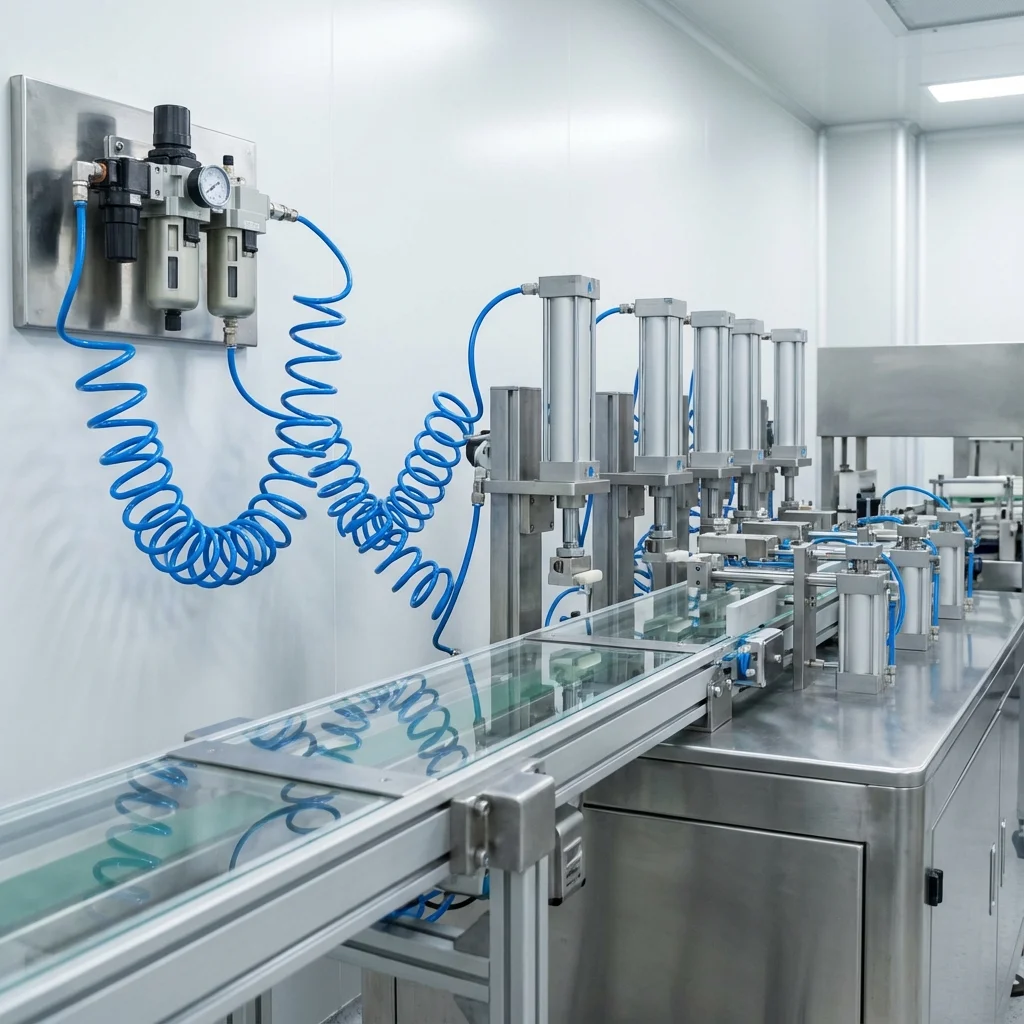
Selecting the correct pneumatic cylinder is not just about fitting a component into a
machine; it's about energy efficiency, cycle speed, and longevity. An
undersized cylinder will cause stalling, while an oversized one wastes expensive
compressed
air.
The Golden Rule
Always apply a safety factor when
sizing
cylinders. For standard applications, select a cylinder that can provide the
required
force at 50% to 70% of the available system pressure.
1. Force Calculation
The theoretical force output of a cylinder is determined by the air pressure and the
effective piston area. The formula is simple but crucial:
F = P × A
- F: Force (Newton)
- P: Pressure (Pascal - Pa) [1 bar = 0.1 MPa]
- A: Area (mm²)
1.1. Double Acting Cylinders
For double-acting cylinders, the force is different for extension (thrust) and
retraction
(pull).
- Extension: Full piston area is used.
- Retraction: Piston rod reduces the effective area.
2. Cylinder Selection Table (at 6 Bar)
The table below shows the theoretical forces for standard ISO 15552 cylinders operating
at 6
bar pressure.
| Diameter (mm) |
Rod Ø (mm) |
Thrust Force (N) |
Pull Force (N) |
|
32
|
12 |
483 |
415 |
|
40
|
16 |
754 |
633 |
|
50
|
20 |
1,178 |
990 |
|
63
|
20 |
1,870 |
1,682 |
|
80
|
25 |
3,016 |
2,721 |
| 100 |
25 |
4,712 |
4,418 |
3. Air Consumption & Efficiency
Calculating air consumption is vital for sizing the compressor and receiver tank. Air
consumption depends on the bore size, stroke, and cycle rate.
Efficiency Tip
Reducing operating pressure from 7 bar to 6 bar can
save
approximately 15% of energy costs without significantly impacting
performance in suitably sized systems.
4. BRS PROSES Selection Support
Our engineering team can assist you with:
- Cycle time analysis
- Buckling load calculations
- Cushioning selection
- Environment-specific seal
selection
(Viton, PU)
6. Dynamic Load Factor ($L_R$) & Sizing for Velocity Profiles
In real-world automation lines, sizing a pneumatic cylinder based on static balance ($F_{ ext{static}} = P cdot A$) guarantees sluggish movement or stalling. Pneumatic cylinders must overcome acceleration forces ($F_a = m cdot a$) and seal friction under dynamic pressure drop. Engineers utilize the Load Ratio ($L_R$):
L_R = \frac{F_{\text{applied load}}}{F_{\text{theoretical}}} = \frac{F_{\text{load}}}{P \cdot \frac{\pi d^2}{4}} \le 0.50\text{ to }0.70
- High-Speed Operation ($v > 0.5 ext{m/s}$): Maintain $L_R le 0.50$ (50% load factor). 50% of available pressure is dedicated purely to rapid acceleration and overcoming exhaust backpressure.
- Standard Cycle Speeds ($v approx 0.1 ext{ to }0.4 ext{m/s}$): Maintain $L_R le 0.70$. Provides robust margins against air supply pressure fluctuations in factory grids.
7. Compressed Air Consumption & Compressor Energy Calculations
Calculating air consumption per double stroke ($V_N$) determines overall plant operating costs and compressor sizing requirements:
| Bore Diameter (Ø) |
Piston Area Forward (cm²) |
Air Consumption per 100 mm Stroke @ 6 Bar (Nl) |
Theoretical Thrust @ 6 Bar (N) |
| Ø32 mm |
8.04 cm² |
0.56 Nl |
482 N (~49 kg) |
| Ø50 mm |
19.63 cm² |
1.37 Nl |
1,178 N (~120 kg) |
| Ø80 mm |
50.27 cm² |
3.52 Nl |
3,016 N (~307 kg) |
| Ø125 mm |
122.72 cm² |
8.59 Nl |
7,363 N (~750 kg) |
Critical Engineering Sizing: Buckling Load & Kinetic Cushioning
Selecting a pneumatic cylinder based solely on static theoretical force is one of the most common causes of premature mechanical failure in automated machinery. In long-stroke applications (> 300 mm) or high-speed cycles (> 0.5 m/s), design engineers must calculate Euler Rod Buckling Safety and Kinetic Energy Absorption Limits to prevent rod deflection, cylinder barrel scoring, and seal destruction.
1. Euler Piston Rod Buckling Calculation (ISO 15552)
When a cylinder is subjected to pushing loads, the slender piston rod acts as an end-loaded column. The permissible thrust force must not exceed the critical Euler buckling limit divided by an engineering safety factor (typically (S ge 3.5) to (5.0)):
F_k = (π² × E × I) / L_k²
• E: Modulus of elasticity of rod material (Steel: 2.1 × 10⁵ N/mm²)
• I: Second moment of area (π × d⁴ / 64 for circular solid rod)
• L_k: Effective buckling length based on mounting geometry (fixed-free, pinned-pinned, or fixed-guided)
2. Kinetic Cushioning Capacity & Deceleration Energy
When the piston approaches the end stroke, the kinetic energy of the moving mass (cylinder piston + rod + external tooling load) must be dissipated by internal pneumatic cushioning chambers or external hydraulic shock absorbers. The kinetic energy is calculated as:
E_kin = (1/2) × m × v² (Joules)
If E_kin exceeds the maximum rated absorption energy of the cylinder end-caps (e.g., max 1.8 J for Ø32mm, max 4.5 J for Ø50mm, max 12.0 J for Ø80mm), heavy mechanical shocks will fracture the end-covers. In such cases, external decelerators must be integrated.
| Bore / Rod Size |
Max Buckling Stroke (at 6 bar push) |
Standard Cushioning Capacity |
Max Speed Limit |
| Ø32 mm (Rod Ø12) |
350 mm (clevis mount) |
1.8 Joules |
800 mm/s |
| Ø50 mm (Rod Ø20) |
500 mm (clevis mount) |
4.5 Joules |
800 mm/s |
| Ø80 mm (Rod Ø25) |
750 mm (clevis mount) |
12.0 Joules |
600 mm/s |
| Ø125 mm (Rod Ø32) |
1100 mm (clevis mount) |
35.0 Joules |
500 mm/s |
Technical Field Inspection & Commissioning Protocol
Prior to signing off on any fluid power retrofit, system upgrade, or routine component overhaul, technical commissioning engineers must rigorously complete the following verification procedures to ensure full compliance with ISO machinery safety standards:
- Static Hydrostatic / Pneumatic Pressure Proof Test: Pressurize circuit to 1.5× maximum design working pressure for 15 minutes, inspecting all welded flanges and fittings for micro-weeping.
- Contamination & Fluid Particle Verification: Draw dynamic fluid samples under working temperature and confirm ISO 4406 cleanliness classes (or ISO 8573-1 air dew point classes) before activating sensitive proportional spool valves.
- Thermal Baseline Profiling: Record continuous thermal infrared scans of pump casings, valve manifold manifolds, and accumulator bodies across 4 hours of full-load production cycles to confirm proper thermal dissipation.
- Failsafe & Emergency De-energization: Verify manual LOTO isolation valves, dump valves, and accumulator vent blocks discharge trapped hydraulic/pneumatic kinetic energy to 0 bar within 2.0 seconds of emergency e-stop triggering.