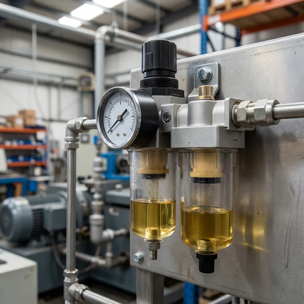
The life of a pneumatic system depends directly on the quality of the compressed air
used.
Air preparation units consisting of Filter, Regulator and Lubricator
(FRL)
are the first line of defense protecting system components against corrosion, wear, and
clogging.
Why Air
Preparation?
Air coming from the compressor is hot, humid, and dirty. If
this
air goes directly to valves or cylinders, it damages seals and causes rusting. The
FRL
unit
cleans the air (F), regulates pressure (R), and lubricates if necessary (L).
FRL Unit Components
1. Filter
Condenses water vapor in the air and traps solid particles. 40 micron
filters
are generally used for standard pneumatic valves, and 5 micron filters
for
precision equipment.
- Centrifugal
Effect: Separates water from the air.
- Automatic
Drain: Allows accumulated water to be discharged without manual
intervention.
2. Regulator
Keeps system pressure constant. Even if the compressor pushes 8-10 bar, the machine
usually
needs 6 bar. The regulator prevents unnecessary air consumption and fluctuations.
Critical Warning: Lubricator
Most modern pneumatic cylinders and valves contain
factory-applied "lifetime lubrication" grease. Adding external lubricant
(conditioner
oil)
to these systems can wash away the internal grease and cause failure.
Do not use a lubricator unless specified by the manufacturer.
ISO 8573-1 Air Quality Standards
International standard determining how clean the air should be
according to
your application.
| Class |
Particle Size (µm) |
Water Pressure Dew Point (°C) |
Oil Quantity (mg/m³) |
| Class 1 |
0.1 - 0.5 |
-70°C |
0.01 |
| Class 2 |
0.5 - 1.0 |
-40°C |
0.1 |
| Class 3 |
1.0 - 5.0 |
-20°C |
1.0 |
| Class 4 |
> 5.0 |
+3°C |
5.0 |
BRS PROSES FRL Solutions
We select the right air preparation units for your industrial facilities, perform their
assembly, and carry out periodic maintenance.
Our Services:
- Air consumption analysis
- Correct filter/regulator selection
- Leak detection and elimination
- Automation panel assembly
BRS PROSES FRL Sizing & Maintenance Checklist
To achieve optimal lifecycle economy from pneumatic air preparation units, system designers must verify nominal air flow velocities through FRL manifold blocks. Sizing piping to maintain air flow velocities below 15 m/s in main distribution headers and below 8 m/s in branch lines prevents excessive dynamic pressure drop ($Delta P > 0.5 ext{bar}$) and ensures moisture coalescence filters function at rated efficiency.
- Filter Differential Pressure Monitoring: Replace particulate and coalescing elements whenever differential pressure indicators exceed 0.35 bar or at 4,000-hour operational intervals.
- Micro-Fog Lubrication Optimization: When lubrication is mandated for heavy air motors, adjust micro-fog lubricators to 1 to 2 oil drops per 1,000 Nl of air using non-detergent ISO VG 32 mineral oil.
- Zero-Air-Loss Electronic Drain Verification: Test capacitive condensate discharge valves weekly to prevent emulsion buildup in receiver tanks.
ISO 8573-1:2010 Air Quality Purity Classes & FRL System Engineering
Compressed air purity is categorized internationally by ISO 8573-1:2010, which classifies contamination levels into three distinct criteria: Solid Particles, Water Dew Point, and Total Oil Content (Aerosol + Vapor). Sizing an FRL (Filter, Regulator, Lubricator) station without knowing the exact ISO class requirements of your downstream valves and cylinders leads to premature component degradation or catastrophic process contamination.
| Application Domain |
ISO 8573-1 Target |
Filtration Chain |
Pressure Dew Point |
| General Machinery & Robotics |
Class [ 7 : 4 : 4 ] |
40 µm Pre-filter + 5 µm Filter |
+3°C (Refrigerant Dryer) |
| High-Speed Proportional Valves |
Class [ 3 : 3 : 2 ] |
5 µm + 0.3 µm Coalescing + Activated Carbon |
-20°C (Desiccant Dryer) |
| Food Packaging & Pharma |
Class [ 1 : 2 : 1 ] |
0.01 µm Micro-Coalescing + Sterile Filter |
-40°C (Twin-Tower Adsorption) |
Critical Maintenance Guidelines for FRL Longevity
1. Differential Pressure Gauges: Install visual pop-up indicators across filter bowls. When (Delta P) exceeds 0.35 bar (5 psi), filter elements must be replaced immediately to prevent flow choking.
2. Auto-Drains vs Manual Drains: Eliminate manual drain petcocks in harsh industrial zones; use zero-air-loss electronic capacitive drain valves to prevent condensate carryover into downstream pneumatic actuators.
Technical Field Inspection & Commissioning Protocol
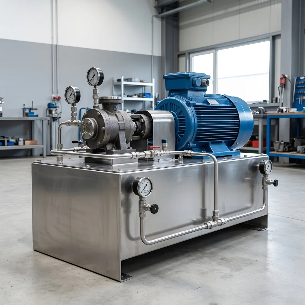
Prior to signing off on any fluid power retrofit, system upgrade, or routine component overhaul, technical commissioning engineers must rigorously complete the following verification procedures to ensure full compliance with ISO machinery safety standards:
- Static Hydrostatic / Pneumatic Pressure Proof Test: Pressurize circuit to 1.5× maximum design working pressure for 15 minutes, inspecting all welded flanges and fittings for micro-weeping.
- Contamination & Fluid Particle Verification: Draw dynamic fluid samples under working temperature and confirm ISO 4406 cleanliness classes (or ISO 8573-1 air dew point classes) before activating sensitive proportional spool valves.
- Thermal Baseline Profiling: Record continuous thermal infrared scans of pump casings, valve manifold manifolds, and accumulator bodies across 4 hours of full-load production cycles to confirm proper thermal dissipation.
- Failsafe & Emergency De-energization: Verify manual LOTO isolation valves, dump valves, and accumulator vent blocks discharge trapped hydraulic/pneumatic kinetic energy to 0 bar within 2.0 seconds of emergency e-stop triggering.