
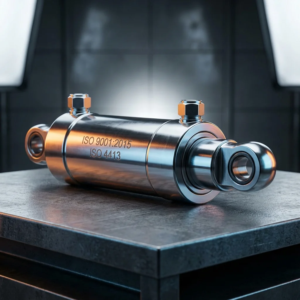

Correct hydraulic cylinder selection directly determines the performance, reliability, and lifespan of the system. Improper sizing can lead to numerous problems, from energy waste to premature failures. In this technical guide, we share the critical engineering parameters and calculation methods that should be potential candidates for cylinder selection.
Basic Formula
F = P × A | Force (kN) = Pressure (bar) × Area (cm²) × 0.1
1. Basic Selection Criteria
Five basic parameters are decisive in hydraulic cylinder selection: required force, stroke distance, operating pressure, movement speed, and operating environment. Correct determination of these parameters is a prerequisite for optimum cylinder selection.
1.1. Force Calculation
The first step is to determine the net force required by the application. Friction losses, load dynamics, and safety factors must be taken into account in calculations.
- Static Load: Nominal force is sufficient for static loads
- Dynamic Load: Acceleration force is added for moving loads
- Safety Factor: Generally applied between 1.25-1.5
1.2. Piston Diameter Determination
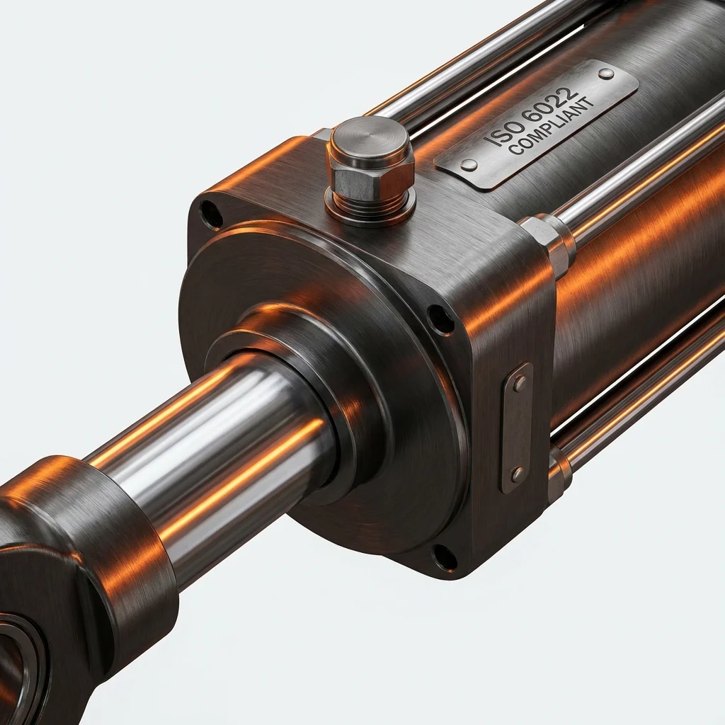
After the required force and operating pressure are determined, the piston diameter is calculated. As BRS PROSES, we manufacture cylinders suitable for ISO 6020/1 and ISO 6022 standards.
| Piston Diameter (mm) | Piston Area (cm²) | Force at 250 bar (kN) | Typical Application |
|---|---|---|---|
| Ø40 | 12.57 | 31.4 | Light Clamping |
| Ø63 | 31.17 | 77.9 | Medium Press Loads |
| Ø100 | 78.54 | 196.4 | Heavy Industry |
| Ø160 | 201.06 | 502.7 | Press Application |
2. Stroke Distance
Stroke distance is the total distance the piston will move. When determining the stroke, application tolerances and additional distance for position sensors must be taken into account. Buckling control is mandatory for long stroke cylinders (over 1000mm).
"Detailed cylinder selection is the foundation of the project. Small errors in diameter, stroke, and pressure calculations turn into large performance losses."
— BRS PROSES Engineering Team
3. Operating Environment Evaluation
Environment Conditions Critical
The operating environment directly affects the selection of cylinder material and seals. The following factors must be evaluated:
- Temperature Range: -20°C to +80°C standard, special seals for extreme conditions
- Corrosive Environment: Stainless steel or chrome plating required
- Dust/Dirt: Rod wiper and protective selection
- Mounting Position: Horizontal, vertical, or angled mounting requirements
4. Connection and Mounting Types
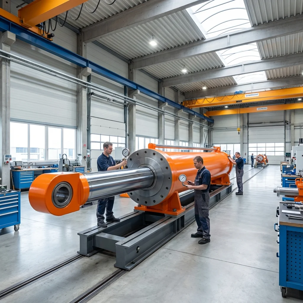
Cylinder mounting type should be selected according to the application. Most common mounting types:
- Flange Mount (MF/MP): For fixed applications
- Clevis Mount (MT/MG): Where angular movement is required
- Eye Type (MS/MH): For pivot connection
- Square Flange (MF4/MF5): Heavy load applications
5. BRS PROSES Cylinder Selection Support
As BRS PROSES, we are with you in your hydraulic cylinder selection with over 25 years of experience. Our engineering team provides:
- Free technical consulting
- Application-based cylinder calculation
- ISO and ECO series standard cylinders
- Custom design cylinder manufacturing
- Fast delivery and technical support
6. Master Fluid Power Regulatory Framework: ISO 4413 & ISO 4414
System engineering compliance in European and international trade hinges upon adherence to the overarching safety standards governing fluid power systems:
- ISO 4413:2010 (Hydraulic Fluid Power Safety): Mandates design safeguards preventing unexpected startup, hydraulic pressure release protocols, hose burst protection, and mechanical cylinder locking in suspended load zones.
- ISO 4414:2010 (Pneumatic Fluid Power Safety): Specifies requirements for compressed air isolation (LOTO), hose whipping prevention restraints, noise level limitations on exhaust ports (<80 dBA via sintered silencers), and pneumatic safety valves with monitored diagnostic coverage.
7. Technical Cross-Reference Matrix: ISO Standards in Fluid Power Engineering
| Standard Code | Technical Domain Covered | Engineering Mandate |
|---|---|---|
| ISO 1219-1 / -2 | Graphic Symbols & Circuit Diagrams | Universal P&ID schematic representation for valves, pumps, and circuits |
| ISO 6020/2 & ISO 6022 | Hydraulic Cylinder Interchangeability | Standardized bore, rod, stroke, and mounting dimensions (160 and 250 bar) |
| ISO 4406:2021 | Hydraulic Fluid Particulate Cleanliness | 3-digit contamination code classifying particles ≥4 μm, ≥6 μm, and ≥14 μm |
| ISO 19973 | Pneumatic Component Reliability ($B_{10d}$) | Mean cycles to failure for functional safety calculations (ISO 13849-1) |
Key International Fluid Power Standards: ISO 4413, ISO 4414 & ISO 1219
Compliance with international technical standards is mandatory for CE marking, machinery safety directives (2006/42/EC), and global cross-border engineering deliveries. Sourcing or designing fluid power machinery according to ISO standards guarantees interoperability, operational safety, and uniform diagnostic routines.
| Standard Code | Standard Title & Scope | Core Safety & Engineering Mandates |
|---|---|---|
| ISO 4413:2010 | Hydraulic Fluid Power - General rules and safety requirements for systems and components | Mandates overpressure relief devices, fluid contamination sampling points, accumulator de-energization dump valves, and hose restraint guards. |
| ISO 4414:2010 | Pneumatic Fluid Power - General rules and safety requirements for systems and components | Requires lockable energy isolation valves (LOTO), exhaust silencer decibel limitations, and whipping hose burst prevention cables. |
| ISO 1219-1 / 2 | Fluid power systems and components - Graphic symbols and circuit diagrams | Defines standardized drafting symbols for valves, pumps, actuators, sensors, and functional designation numbering (e.g. 1A1, 1V1). |
Technical Field Inspection & Commissioning Protocol
Prior to signing off on any fluid power retrofit, system upgrade, or routine component overhaul, technical commissioning engineers must rigorously complete the following verification procedures to ensure full compliance with ISO machinery safety standards:
- Static Hydrostatic / Pneumatic Pressure Proof Test: Pressurize circuit to 1.5× maximum design working pressure for 15 minutes, inspecting all welded flanges and fittings for micro-weeping.
- Contamination & Fluid Particle Verification: Draw dynamic fluid samples under working temperature and confirm ISO 4406 cleanliness classes (or ISO 8573-1 air dew point classes) before activating sensitive proportional spool valves.
- Thermal Baseline Profiling: Record continuous thermal infrared scans of pump casings, valve manifold manifolds, and accumulator bodies across 4 hours of full-load production cycles to confirm proper thermal dissipation.
- Failsafe & Emergency De-energization: Verify manual LOTO isolation valves, dump valves, and accumulator vent blocks discharge trapped hydraulic/pneumatic kinetic energy to 0 bar within 2.0 seconds of emergency e-stop triggering.