1. Introduction to Valve Dynamics in Industrial Plants
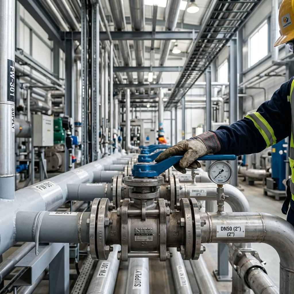
In complex industrial plants, spanning from chemical processing and petrochemical refining to power generation and water treatment, valves serve as the primary control nodes governing the mass and energy transport throughout the piping networks. Choosing the optimal valve is not merely a purchasing decision based on pipe diameter; it is a critical engineering task that demands a deep understanding of fluid mechanics, thermodynamics, material science, and control theory.
A poorly specified valve introduces profound inefficiencies. Oversizing a control valve leads to poor throttling resolution and "hunting" near the closed position, whereas undersizing creates excessive pressure drops, high flow velocities, and unrecoverable energy losses. Furthermore, an incorrect valve type can induce destructive phenomena such as cavitation, flashing, and water hammer, significantly shortening the lifespan of both the valve and adjacent piping components.
2. Pressure-Temperature (P-T) Ratings and Flange Standards
The fundamental constraint in valve selection is its ability to withstand the internal energy of the fluid. This is quantified by Pressure-Temperature (P-T) ratings, typically standardized under ASME B16.34 (for ANSI classes like 150, 300, 600) or EN 1092-1 (for PN designations like PN16, PN40). A critical engineering error is assuming that a valve rated for a specific pressure can sustain that pressure at all operating temperatures.
As temperature increases, the yield strength and tensile strength of the valve body material degrade. For instance, a Class 300 carbon steel (ASTM A216 WCB) valve might safely contain 51 bar (740 psi) at ambient temperature, but its safe working pressure drops precipitously to around 28 bar (410 psi) at 400°C. Engineers must map the entire operational envelope—including startup, shutdown, and extreme excursion scenarios—against the material's P-T curve. Thermal shock and differential thermal expansion between the valve body, trim, and stem must also be evaluated, particularly in cryogenic or high-temperature steam applications.
3. Fluid Mechanics: Cavitation, Flashing, and Choked Flow
When analyzing liquid flow through a valve, the vena contracta—the point of minimum cross-sectional flow area just downstream of the valve restriction—is the focal point of hydrodynamic instability. At this locus, fluid velocity is maximized, and consequently, localized static pressure drops to its absolute minimum according to Bernoulli's principle.
If this localized pressure falls below the fluid's vapor pressure (Pv) at the operating temperature, vapor bubbles spontaneously form. If the pressure subsequently recovers above Pv further downstream, these bubbles violently implode. This phenomenon, known as cavitation, generates localized shockwaves with micro-jet impacts exceeding 100,000 psi, rapidly eroding the valve trim (a destructive signature often resembling pitted sponge or "swiss cheese"). To mitigate cavitation, engineers utilize multi-stage anti-cavitation trims (e.g., tortuous path or drilled cylinder cages) that drop the pressure in successive, controlled stages, ensuring the localized pressure never dips below Pv.
Conversely, if the downstream pressure remains below Pv, the fluid remains in a two-phase state (liquid and vapor). This is called flashing. Flashing is highly erosive due to the high-velocity, two-phase jet. Material hardening (e.g., Stellite overlay on seating surfaces) and angled valve bodies (to direct the flashing jet away from the valve walls) are standard countermeasures.
4. Valve Types and Kinematic Profiles
The mechanical kinematics of the obturator (the closing element) dictates the valve's suitability for specific tasks: isolation (on/off), throttling (control), or unidirectional flow (check).
4.1. Ball Valves (Rotary/Quarter-Turn)
Characterized by a spherical obturator with a bore, ball valves provide a nearly unobstructed flow path when fully open, resulting in exceptionally low pressure drop and high flow capacity. They are the premier choice for rapid, bubble-tight isolation. However, standard floating ball valves exhibit terrible throttling characteristics; opening them partially exposes the soft PTFE seats to high-velocity flow, leading to rapid seat degradation. For severe service, trunnion-mounted ball valves with metal-to-metal seating (often tungsten carbide coated) are utilized.
4.2. Butterfly Valves
Utilizing a rotating disc, butterfly valves are compact, lightweight, and highly cost-effective for large-diameter pipelines. While concentric butterfly valves are adequate for low-pressure utility water, high-performance applications demand double-offset or triple-offset eccentric designs. A triple-offset butterfly valve (TOV) employs an asymmetrical conical seating geometry, ensuring the disc contacts the seat only at the final moment of closure, eliminating rubbing and enabling bubble-tight shutoff even under severe thermal cycling.
4.3. Globe and Control Valves (Linear Motion)
The tortuous flow path of a globe valve inherently introduces significant pressure loss, but it allows for precise, stable modulation of flow. In automated process control, cage-guided globe valves are the industry standard. The cage serves a dual purpose: it guides the plug, preventing vibration induced by fluid momentum, and its profiled windows dictate the valve's inherent flow characteristic—typically linear, equal percentage, or quick-opening.
"A control valve's 'equal percentage' trim is mathematically designed so that equal increments of valve travel produce equal percentage changes in the existing flow coefficient (Cv). This non-linear inherent characteristic brilliantly compensates for the non-linear pressure drop typical in long piping systems, resulting in a linear installed characteristic—the holy grail of process control stability."
— BRS PROSES Fluid Dynamics Division
5. Actuation and Smart Control Loops
Modern industrial valves are rarely manually operated; they are integrated into sophisticated Distributed Control Systems (DCS) via pneumatic, hydraulic, or electric actuators. Pneumatic diaphragm and piston actuators remain dominant due to their fail-safe reliability (using mechanical springs to drive the valve to a safe position upon air failure) and rapid response times.
The brain of a control valve is the digital smart positioner. Operating via protocols like HART, Foundation Fieldbus, or Profibus, the positioner continuously compares the DCS setpoint with the actual valve stem position via a Hall-effect sensor. Advanced microprocessor-based positioners execute complex PID algorithms locally, compensating for valve stiction and hysteresis. Furthermore, they provide continuous diagnostic telemetry, monitoring parameters such as air consumption, friction signatures, and dynamic error bands, enabling predictive maintenance models that flag impending failures long before a process upset occurs.
6. Material Science and Corrosion Engineering
Valve metallurgy must be meticulously tailored to the chemical aggressiveness and abrasive nature of the media. General service cooling water allows for ductile iron or carbon steel (WCB/WCC) bodies. However, acidic or chloride-rich environments demand austenitic stainless steels (316/316L). For highly localized pitting and crevice corrosion resistance in seawater or sour gas (H2S) applications, duplex or super-duplex stainless steels (e.g., SAF 2507) or high-nickel alloys like Hastelloy, Inconel, and Monel are mandatory, strict compliance with NACE MR0175/ISO 15156 is critical to prevent sulfide stress cracking.
Internal trim hardening is equally crucial. Stellite (a cobalt-chromium alloy) overlays are routinely applied to seat rings and plugs to combat erosion, galling, and cavitation damage. For severe abrasive slurries (e.g., mining tailings), solid ceramic trims or polyurethane-lined bodies are specified.
7. Valve Sizing Calculations: The Flow Coefficient (Cv & Kv)
Proper valve sizing requires rigorous mathematical calculation of the flow coefficient. The Imperial Cv represents the volume of water (in US gallons per minute) at 60°F that will flow through the valve with a pressure drop of 1 psi. The metric equivalent is Kv (cubic meters per hour with a 1 bar pressure drop). The fundamental equation for liquid flow involves comparing flow rate, specific gravity, and the pressure differential.
However, this simplified equation fails under choked flow conditions. When the pressure drop exceeds the critical threshold, further lowering downstream pressure will not increase flow rate, as the fluid has reached its thermodynamic limit (vaporizing at the vena contracta). Engineers must utilize the Liquid Pressure Recovery Factor (FL) to predict the onset of choked flow and size the valve based on the allowable pressure drop rather than the actual downstream pressure drop. Sizing for compressible gases and steam involves even more complex equations incorporating expansion factors (Y) and heat capacity ratios.
Optimal sizing dictates that the valve should operate between 20% and 80% of its travel during normal conditions. Operating below 10% risks mechanical damage to the plug and seat due to high-velocity clearances, while operating above 90% leaves no dynamic margin to respond to sudden process demands.
8. Frequently Asked Questions
Preventing cavitation requires careful engineering. First, ensure the valve is sized correctly to minimize excessive pressure drops. If a high pressure differential is unavoidable, use a valve with a high Liquid Pressure Recovery Factor (FL), or specify multi-stage anti-cavitation trim. These trims drop the pressure incrementally, ensuring localized pressure never dips below the fluid's vapor pressure. Alternatively, placing an orifice plate downstream can distribute the pressure drop and provide backpressure to the valve.
ANSI (ASME) classes (e.g., 150, 300, 600) are Imperial standards based on pressure-temperature ratings for specific materials. PN (Pressure Nominal) is a European metric standard indicating the maximum allowable working pressure at room temperature in bars (e.g., PN16 = 16 bar at ~20°C). They are not perfectly interchangeable. For example, an ANSI Class 150 carbon steel flange can handle roughly 19.6 bar at ambient temperature, making it roughly comparable to, but slightly stronger than, a PN16 flange, but weaker than a PN25.
Standard floating ball valves are designed for fast, tight on/off isolation. If you leave them partially open, the high-velocity fluid jets across the soft polymeric seats (like PTFE). This causes rapid erosion ("wire drawing") and can deform the seat. Eventually, the valve will fail to seal tightly when closed. For throttling, you should use a globe valve, V-port ball valve, or specialized rotary control valve.
Choked flow is a thermodynamic limit. Normally, increasing the pressure difference across a valve increases the flow rate. However, if the pressure drops so much that the liquid vaporizes (flashing/cavitation) or a gas reaches sonic velocity (Mach 1) at the vena contracta, the fluid velocity cannot increase any further. At this point, lowering the downstream pressure will not yield any more flow. Sizing equations must correct for this state using the FL or Y factors.