In industrial manufacturing environments, excessive acoustic noise and mechanical vibration emanating from a hydraulic power unit (HPU) are frequently dismissed as inevitable operational nuisances. However, from a precision engineering standpoint, acoustic energy is an undeniable thermodynamic symptom of mechanical inefficiency, fluid instability, or structural stress. Whether manifesting as high-frequency whining, rhythmic thumping, or gravel-like grinding, noise serves as the earliest physical telegraph of impending mechanical failure. Treating hydraulic noise purely through superficial soundproofing without diagnosing the root hydrodynamic and mechanical causes merely masks progressive damage, accelerating component destruction and risking catastrophic line shutdowns.
What Are the Underlying Sources of Hydraulic Noise and Vibration?
A comprehensive acoustic audit requires categorizing noise into its three interconnected propagation pathways: airborne noise, fluid-borne noise, and structure-borne vibration. Each pathway demands distinct diagnostic instruments and targeted mitigation strategies:
- Fluid-Borne Noise (Pressure Ripples & Pulsation): Positive displacement pumps (gear, vane, piston) deliver fluid in discrete volumetric chambers. The opening and closing of pumping chambers inevitably induces cyclic pressure ripples (±5% to ±20% of nominal system pressure). These high-velocity pulsations travel through the fluid column at the speed of sound in oil (~1200–1400 m/s), impinging on directional valves, elbows, and manifolds.
- Structure-Borne Noise (Mechanical Excitation): Cyclic forces generated by pump rotating groups, shaft misalignments, and valve spool impacts transmit vibrational energy directly into the pump casing, bellhousing, motor brackets, and reservoir top plate. If the excitation frequency coincides with the natural frequency of the oil reservoir or piping supports, structural resonance amplifies acoustic radiation exponentially.
- Airborne Noise (Direct Sound Radiation): The physical surfaces of electric motors, cooling fans, vibrating reservoir side panels, and uninsulated valve manifolds radiate acoustic pressure waves directly into the ambient factory atmosphere.
Critical Diagnostic Rule: Diagnosis Must Precede Acoustic Enclosure
Enclosing a noisy hydraulic power unit within an insulated acoustic booth without diagnosing the root cause is a dangerous maintenance shortcut. If the noise originates from cavitation, air entrainment, or bearing misalignment, acoustic cladding will trap operating heat while allowing pump internal destruction to accelerate undetected, culminating in sudden catastrophic failure.
Acoustic Fundamentals: The Logarithmic 3 dB(A) Energy Rule & ISO 3744 Standards
Managing industrial noise cannot rely on subjective human impressions such as "sounds quieter." Sound pressure level is quantified logarithmically in decibels (dB), specifically utilizing the A-weighting scale (dB(A)) defined in IEC 61672-1, which matches the sensitivity profile of the human ear across middle and high frequencies.
Because decibels follow a logarithmic scale ($L_p = 10 \log_{10}(P^2 / P_0^2)$), a 3 dB(A) increase represents an exact doubling of acoustic sound energy. Conversely, an engineering modification that reduces system sound from 88 dB(A) down to 82 dB(A)—nominally a change of "only 6 decibels"—actually removes 75% of the total acoustic energy radiating into the workspace. In jurisdictions governed by OSHA (USA) or Directive 2003/10/EC (European Union), the mandatory continuous 8-hour occupational exposure limit is 85 dB(A). Exceeding this threshold obligates manufacturers to implement mandatory hearing protection and documented engineering noise reduction programs.
At BRS PROSES, acoustic field assessments follow the ISO 3744 standard, which determines sound power levels using multi-microphone hemispherical enveloping surfaces around the operating machine. Measurements are taken at nominal operating pressure, maximum flow, and relief valve bypass states across operators' actual breathing zones.
| Industrial Acoustic Environment / Source |
Typical Noise Level |
Engineering Significance & Action Threshold |
| Quiet Engineering Office Baseline |
45–52 dB(A) |
Standard ambient baseline reference |
| Acoustically Cladded HPU (1 meter distance) |
62–70 dB(A) |
Optimized benchmark; unrestricted continuous operator presence |
| Standard Industrial HPU (Uninsulated, 1 m) |
76–84 dB(A) |
Acceptable for general shop floor; borders statutory limit |
| Statutory 8-Hour Workplace Limit (OSHA / EU) |
85 dB(A) |
Legal ceiling; mandatory engineering noise abatement controls |
| Cavitation or Severe Pump Distress |
90–98 dB(A) |
Immediate shutdown warning; destructive mechanical pitting occurring |
How Does Pump Architecture Affect System Noise Levels?
The initial hardware selection of the hydraulic pump dictates the inherent acoustic baseline of the power unit. Operating at identical pressures and volumetric flow rates, two pumps of differing internal geometries can produce acoustic disparities exceeding 12 dB(A).
| Pump Architecture |
Typical Noise @ Full Load |
Flow Ripple % |
Pressure Envelope |
Acoustic Characteristic |
| External Gear Pump |
76–86 dB(A) |
12%–18% |
Up to 250 bar |
High-frequency meshing whine; high ripple |
| Internal Gear Pump (Crescent) |
64–72 dB(A) |
3%–5% |
Up to 300 bar |
Extremely quiet; smooth radial sealing profile |
| Vane Pump (Balanced Dual-Chamber) |
68–76 dB(A) |
4%–7% |
Up to 210 bar |
Low-vibration broadband hum; ideal for machine tools |
| Fixed Axial Piston Pump |
74–82 dB(A) |
6%–10% |
Up to 350+ bar |
Mechanical slipper clatter; valve plate transition pulses |
| Variable Displacement Swashplate Piston |
68–76 dB(A) |
3%–6% |
Up to 420 bar |
De-strokes at holding pressure; exceptionally quiet at dwell |
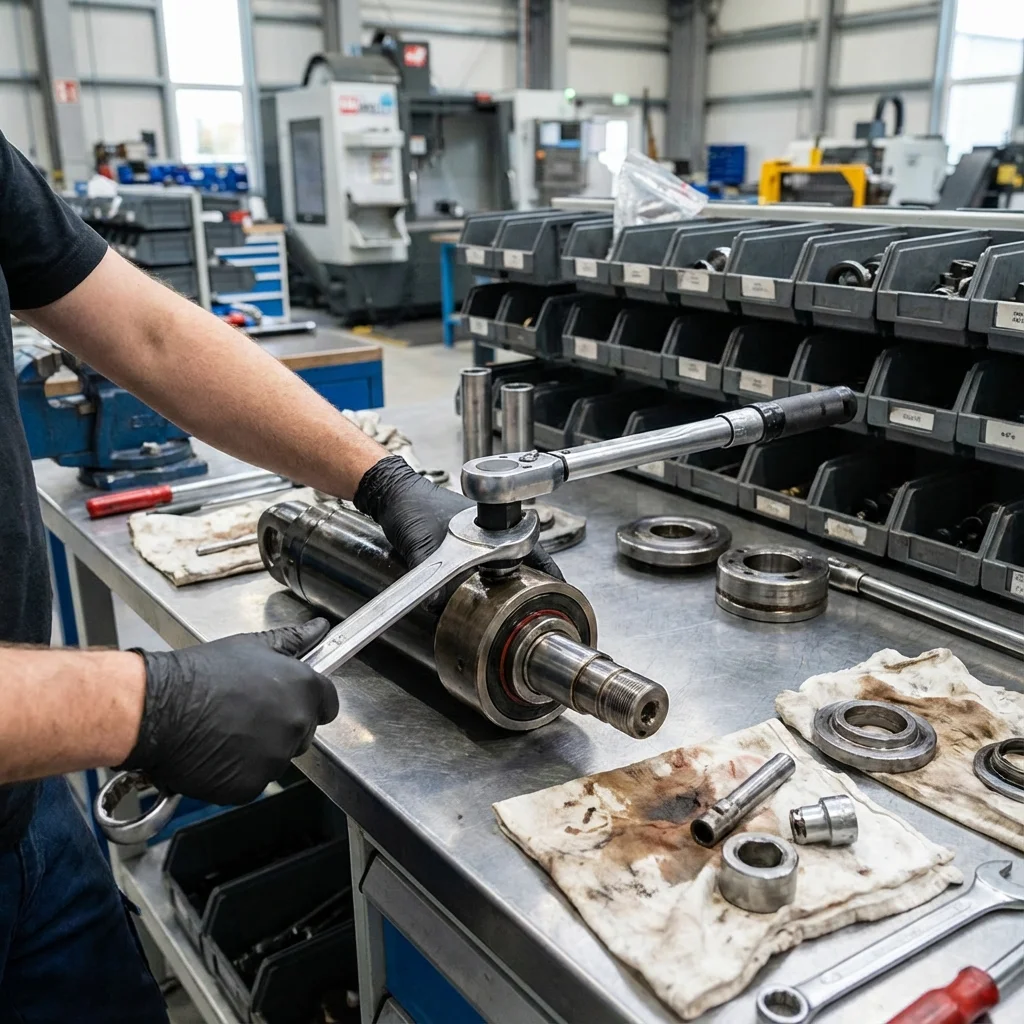
Testing facility: Dynamic acoustic and modal frequency characterization.
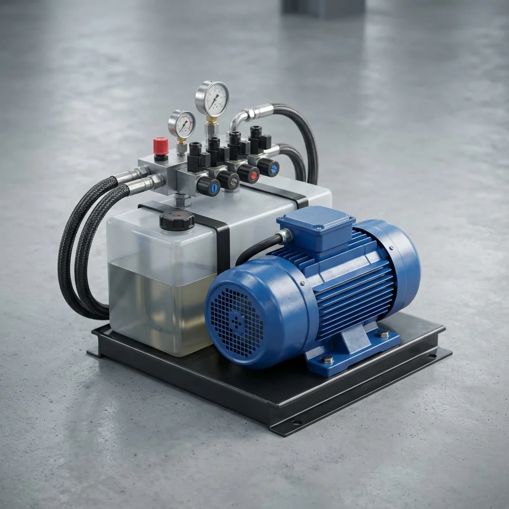
Studio view: HPU engineered with elastomer decoupling mounts and pulsation dampening.
Cavitation and Aeration: Eliminating Destructive Fluid Instabilities
True cavitation occurs when local hydraulic fluid pressure drops below the saturated vapor pressure of the mineral oil (typically near absolute vacuum), causing volatile fluid fractions to flash into vapor bubbles. As these micro-bubbles enter the high-pressure discharge zone (100–350 bar), they implode violently within microseconds. Micro-jets exceed 1000 m/s with localized localized shock pressures surpassing 10,000 bar. This creates an unmistakable gravel-like grinding noise while ripping microscopic metallic flakes from pump port plates and cylinder barrels.
Aeration, by contrast, is the entrainment of atmospheric air bubbles within the oil matrix. Air is highly compressible; when pressurized, air bubbles undergo severe adiabatic compression, reaching localized temperatures above 1000°C (the "Diesel effect"), scorching the oil, oxidizing additives, and generating loud popping sounds.
To eliminate cavitation and aeration at the engineering design stage, BRS PROSES enforces five rigorous physical design constraints:
- Suction Line Fluid Velocity (≤ 1.0 m/s): Suction lines must be oversized to restrict flow velocity strictly below 0.8–1.2 m/s, preventing vacuum pull during cold startups.
- Net Positive Suction Head (NPSH) Verification: Ensuring positive head pressure on pump suction ports by mounting the pump below minimum reservoir oil level whenever feasible.
- Diffuser Return Lines & Internal Baffle Plates: Return pipes must terminate at a 45-degree angle below the minimum oil level facing away from the suction intake. High-efficiency baffle plates force returning oil through a settling maze, allowing entrained bubbles to de-aerate prior to re-entering the pump inlet.
- High-Quality Anti-Wear (AW) Oils with Anti-Foam Additives: Utilizing ISO VG 46/68 fluids conforming to DIN 51524-2 (HLP) with rapid air release properties (ISO 6614 < 7 minutes).
Piping Network Dynamics: Acoustic Resonance Suppression & Hose Selection
Rigid steel piping lines act as acoustic waveguides. When pump discharge ripple frequencies coincide with the acoustic natural frequency of a pipe segment ($f_n = c / (2L)$ where $c$ is speed of sound in oil), standing acoustic waves form, amplifying pressure pulsation by up to 400%.
To decouple fluid-borne ripples and suppress piping vibration, BRS PROSES applies the following structural guidelines:
- Flexible Elastomeric Hose Decoupling: Installing a flexible high-pressure wire-braid hose (EN 857 2SC or EN 856 4SP) immediately between the pump discharge port and the rigid steel manifold. The volumetric expansion of the elastomer absorbs pulsation energy, isolating structural transmission.
- Pressure Line Fluid Velocity (3.5–5.0 m/s): Maintaining moderate fluid velocity in high-pressure lines to eliminate turbulent boundary layer separation and localized vortex shedding at elbows and tee-junctions.
- Vibration Damping Pipe Clamps (DIN 3015): Rigid pipe welds must never be bolted directly to machine steel frames. Clamps conforming to DIN 3015 utilizing elastomer-lined polypropylene (PP) or polyamide (PA) cushions absorb transverse vibratory energy. Clamps are spaced irregularly to prevent harmonic reinforcement.
- Bladder-Type Pulsation Dampeners: For critical high-pressure piston circuits, compact inline bladder accumulators charged with nitrogen to 60%–70% of working pressure absorb peak flow ripples, reducing pressure ripple amplitude by up to 85%.
"Acoustic noise in fluid power systems is not an arbitrary defect; it is a high-resolution frequency broadcast revealing the precise thermodynamic and mechanical state of your machinery. Systems engineered with proper suction hydraulics, elastomeric decoupling, and acoustic damping operate whisper-quiet, consume less electrical energy, and run reliably for decades."
— BRS PROSES Noise & Vibration Engineering Specialist Group
Engineering Industrial Acoustic Enclosures (Acoustic Hoods)
Once mechanical balance and hydrodynamic instabilities have been fully optimized, the remaining airborne noise radiating from the motor-pump group can be addressed through custom-engineered acoustic enclosures. Designing an industrial enclosure requires balancing acoustic transmission loss with thermal heat rejection:
- Composite Multi-Layer Wall Construction: Enclosure shells feature 2 mm heavy gauge steel exterior skins, a viscoelastic damping membrane, and 50–80 mm of high-density rockwool or open-cell polyurethane foam with perforated aluminum retention facings (Sound Transmission Class STC ≥ 35).
- Labyrinth Acoustic Ventilation Silencers: Electric motors and oil reservoirs generate continuous thermal heat. Direct wall cutouts for fans destroy acoustic containment. Ventilation air must enter and exit through acoustic labyrinth splitters lined with absorption baffles that force sound waves through multiple 90-degree reflections, attenuating airborne sound while permitting convective airflow.
- Quick-Release Maintenance Access: Daily inspection points (oil level sight glasses, differential pressure filter gauges, diagnostic sample ports) must be accessible through sealed, acoustic-rated acrylic inspection windows and heavy-duty latched hatches. If routine maintenance requires disassembling the enclosure, maintenance personnel will inevitably leave panels off, nullifying the investment.
Field Case Study: 92 dB(A) Forging Press Noise Reduced to 68 dB(A)
In an automotive stamping facility in Bursa, an existing 400-ton hydraulic press generated an unbearable 92 dB(A) noise level across the operator workstation. Plant management initially solicited quotes to erect a massive structural sound booth around the entire machine. BRS PROSES conducted an ISO 3744 modal acoustic audit, revealing that the true noise root cause was two-fold:
- Severe Intake Choking: A restrictive 2-inch suction line combined with a partially blinded 125-micron intake strainer produced a suction vacuum of −0.45 bar, inducing severe continuous cavitation across the 180 cc/rev variable piston pump.
- Structural Resonance Amplification: The pump discharge steel pipe was hard-welded to the reservoir side plate, transforming the 2000-liter oil tank into an enormous acoustic resonator vibrating at the 145 Hz pump piston passing frequency.
BRS PROSES enlarged the suction header to 3.5 inches, replaced the restrictive strainer with an external suction shut-off valve and high-flow cleanable filter, inserted a flexible SAE 100 R13 decoupling hose on the pressure port, and remounted the pump-motor assembly on tuned elastomeric rail isolators. These mechanical root-cause modifications reduced noise from 92 dB(A) to 76 dB(A) before any enclosure was added. Subsequent installation of a compact, modular acoustic hood dropped workstation noise to an unprecedented 68 dB(A), allowing clear verbal communication without ear defenders.
Conclusion: The Systematic Pathway to Whisper-Quiet Hydraulics
Noise and vibration control in industrial fluid power is a rigorous discipline of physics, fluid mechanics, and structural dynamics. By systematically identifying excitation sources, restoring hydrodynamic balance, isolating structure-borne vibration, and attenuating airborne radiation, BRS PROSES transforms harsh, vibrating hydraulic machinery into silent, energy-efficient, and long-lasting production assets.