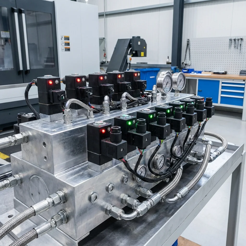
Hydraulic valves are the brain of the system. They control the
direction, pressure, and flow rate of the fluid, ensuring the machine operates as
desired. In this guide, we examine in detail the valve types used in industrial
applications, their working principles, and selection criteria.
Basic Knowledge
Hydraulic valves are divided into three main
categories:
Directional Control Valves, Pressure Control
Valves,
and
Flow Control Valves. Each category offers solutions for different
system needs.
1. Directional Control Valves
Directional control valves are the primary routing mechanisms within a hydraulic circuit, determining the path that the hydraulic fluid takes. By establishing specific connections between the pump, actuators, and the reservoir, these valves control the start, stop, and direction of motion of cylinders and hydraulic motors. The precision of a directional valve dictates the overall synchronization and responsiveness of the machine cycle.
1.1. Nomenclature and Port Configurations
Directional valves are designated by a standardized numerical format representing the number of ports / number of positions. For instance, a 4/3-way valve denotes a valve with 4 main hydraulic ports and 3 distinct switching positions.
- P (Pump): Pressure inlet port connected directly to the hydraulic pump supply line.
- T (Tank): Return port that channels fluid back to the hydraulic reservoir under low pressure.
- A & B (Actuator): Working ports connected to the hydraulic cylinder or motor.
- X & Y (Pilot): External pilot pressure and drain ports typically found in pilot-operated large-scale valves.
| Configuration |
Spool Center Types (for 3-pos) |
Technical Application & Behavior |
| 2/2-Way Poppet |
N/A (Open/Closed) |
Leak-free isolation, holding loads indefinitely against gravity, emergency stop logic. |
| 4/3-Way Closed Center |
All ports blocked (P, T, A, B isolated) |
Holds actuator in position. Requires relief valve. Accumulator circuits to maintain system pressure. |
| 4/3-Way Tandem Center |
P connected to T; A & B blocked |
Unloads pump to tank to save energy/reduce heat when idle. Actuator locked in position. |
| 4/3-Way Motor Center |
A & B connected to T; P blocked |
Allows hydraulic motors to freewheel or coast to a stop. Prevents cavitation. |
1.2. Direct vs. Pilot Operated Actuation
Direct-acting solenoid valves are limited by the physical magnetic force the coil can generate against flow forces. Typically, they handle up to 100-120 L/min. For higher flow rates (up to thousands of liters per minute), pilot-operated directional valves are mandatory. In these, a smaller direct-acting pilot valve uses system pressure to shift the main spool, overcoming immense hydrodynamic forces.
2. Pressure Control Valves
Pressure control valves are the primary safety and force-regulation devices in a hydraulic system. Since force is a direct product of pressure and area (F = P × A), these valves are strictly responsible for regulating the physical output force of actuators and protecting components from catastrophic bursting.
2.1. Critical Pressure Valve Topologies
-
Pressure Relief Valves (PRV)
The most vital safety component. Placed in parallel with the pump, it remains normally closed. When system pressure overcomes the adjustable spring setting, the poppet unseats, bypassing fluid back to the tank to cap the maximum system pressure.
-
Pressure Reducing Valves
Unlike relief valves, these are normally open and placed in series with a sub-circuit. They monitor downstream pressure. When downstream pressure rises to the setting, the spool partially closes to restrict flow, maintaining a lower, constant pressure in that specific branch regardless of higher main system pressure.
-
Counterbalance (Overcenter) Valves
Essential for handling overrunning or suspended loads (e.g., crane winches, press cylinders). They create backpressure to prevent the load from free-falling faster than the pump can supply fluid, eliminating dangerous cavitation and runaway conditions.
Critical Safety Warning
Operating any positive-displacement hydraulic pump without a properly sized and calibrated pressure relief valve is extremely hazardous. Deadheading a pump can result in pressure spikes that cause catastrophic hose bursts, housing fractures, and severe injury within milliseconds.
3. Flow Control Valves & Speed Regulation
Flow control valves regulate the volumetric rate of fluid transfer, which directly dictates the speed of hydraulic cylinders (v = Q / A) and the rotational RPM of hydraulic motors.
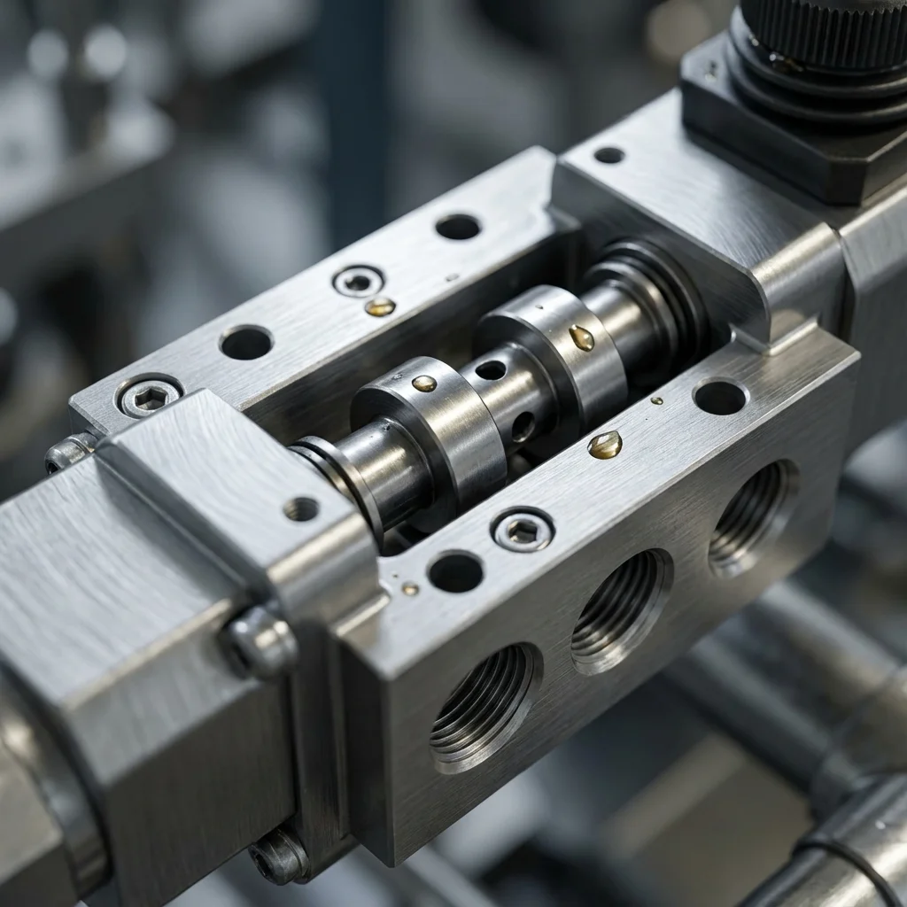
Fig 1: Sectional view of a precision flow control restrictor.
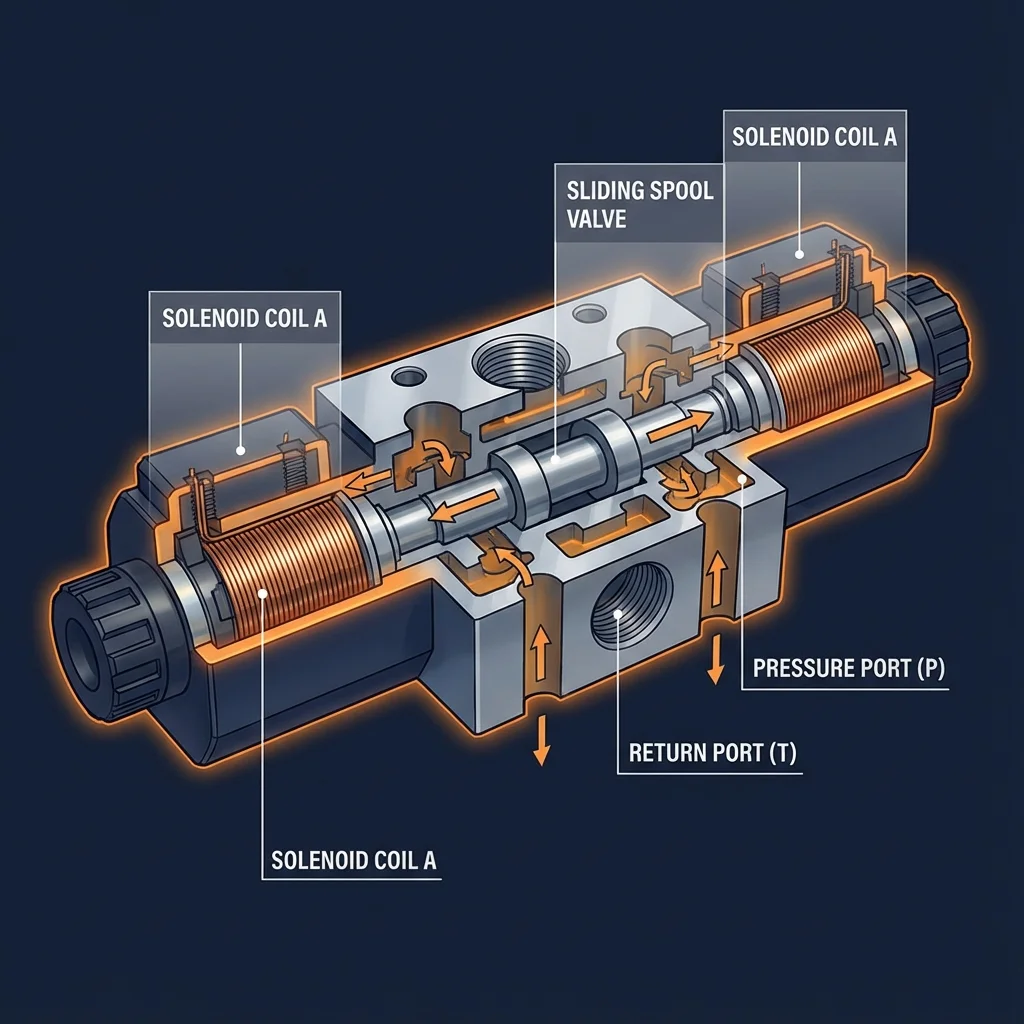
Fig 2: Internal spool and spring architecture.
3.1. Pressure-Compensated vs. Non-Compensated
Non-compensated throttle valves act like a simple pinched hose. The flow rate through them will fluctuate if the pressure drop across the valve changes (e.g., if the load on the cylinder suddenly increases).
Pressure-compensated flow control valves incorporate an internal hydrostat (compensator spool) that continuously adjusts to maintain a constant pressure drop across the main orifice. This guarantees a highly stable flow rate—and therefore constant actuator speed—regardless of load variations or pump pressure fluctuations.
3.2. Meter-In vs. Meter-Out Circuits
How a flow control valve is installed heavily influences system dynamics. Meter-In restricts fluid entering the actuator, suitable for resisting loads. However, for loads that tend to run away or pull the cylinder (overrunning loads), Meter-Out is required. Meter-out restricts the fluid leaving the actuator, creating a stable backpressure that firmly holds the load back.
4. Advanced Proportional and Servo Valve Technologies
Modern Industry 4.0 applications demand more than simple ON/OFF ("bang-bang") control. Proportional and servo valves bridge the gap between heavy mechanical fluid power and precise electronic intelligence.
4.1. Proportional Directional Valves
Proportional valves use variable-current solenoids (controlled via PWM amplifiers) to shift the spool to infinite positions between fully open and fully closed. This allows a single valve to control both the direction and the acceleration/deceleration (flow rate) of the actuator. Built-in LVDT (Linear Variable Differential Transformer) sensors monitor the exact spool position and feed it back to the onboard electronics, correcting for flow forces and hysteresis.
4.2. High-Response Servo Valves
Servo valves operate on a different internal architecture, typically using a torque motor and a flapper-nozzle or jet-pipe pilot stage. They are engineered for aerospace-grade precision and closed-loop control systems. They offer near-zero deadband, extreme linearity, and step-response times under 10 milliseconds. Applications include flight simulators, plastic injection molding injection profiling, and dynamic materials testing machines.
"The integration of onboard digital electronics in modern servo-proportional valves has shifted hydraulic system tuning from mechanical wrenching to software parameterization via Fieldbus networks."
— System Architecture Team, BRS PROSES
5. Troubleshooting & Maintenance of Hydraulic Valves
Even the highest quality valves fail if fluid conditioning is neglected. Over 80% of hydraulic valve failures are directly attributable to fluid contamination.
- Spool Sticking (Silting): Microscopic clearance between the spool and bore (often 2-5 microns) can become jammed by silt-sized particles. Strict adherence to ISO 4406 cleanliness codes (e.g., 18/16/13 for proportional systems) is mandatory.
- Solenoid Burnout: If an AC solenoid spool is physically jammed and cannot complete its stroke, the initial high "inrush" current will not drop to the lower "holding" current, melting the coil within minutes. DC solenoids do not suffer from inrush current burnout, but performance degrades drastically when hot.
- Cavitation Erosion: If pressure drops below the fluid's vapor pressure near the valve notches (vena contracta), vapor bubbles form and violently collapse, tearing metal from the spool lands. Ensure proper backpressure and avoid overly aggressive throttling.
- Varnish Formation: Fluid oxidation due to high operating temperatures (>65°C / 150°F) creates a sticky resin that coats valve internals, leading to sluggish response and hysteresis in proportional valves.
// 1. Force Output of a Cylinder
Force (N) = Pressure (bar) × Area (cm²) × 10
// 2. Flow Rate & Actuator Speed
Speed (m/s) = [Flow (L/min) × 21.22] / [Diameter² (mm)]
// 3. Valve Flow Coefficient / Pressure Drop
Q = Cv × √(ΔP / Specific Gravity)
7. Frequently Asked Questions (FAQ)
What is the difference between open-center and closed-center directional valves?
In an open-center valve, the pump flow returns freely to the tank when the valve is in the neutral position. This is common in simple, fixed-displacement gear pump circuits. In a closed-center valve, all ports are blocked in neutral, allowing system pressure to remain high for immediate response, typically used with variable displacement, pressure-compensated pumps.
Why do hydraulic valves hum or chatter?
Chatter is usually caused by instability in the pressure relief or counterbalance valve. It occurs when flow is too low to keep the poppet fully open, causing it to bounce rapidly against its seat. It can also indicate entrained air in the oil, worn pilot seats, or improper spring adjustment.
How often should valve O-rings be replaced?
Static O-rings under valve blocks generally last 3 to 5 years depending on operating temperature and fluid compatibility. However, if the system runs consistently above 70°C (158°F), standard Nitrile (Buna-N) seals will harden and crack much sooner. Upgrading to Viton (FKM) is recommended for high-heat applications.
Can I replace a standard bang-bang valve with a proportional valve directly?
Mechanically, yes, as long as the mounting pattern (e.g., CETOP 3 / NG6) matches. However, electrically, you cannot drive a proportional valve with a standard 24V relay. You will need a specialized PWM amplifier card, a continuous analog command signal (like 0-10V or 4-20mA) from a PLC, and significantly stricter fluid filtration.
8. BRS PROSES Valve Solutions
At BRS PROSES, our fluid power division provides end-to-end engineering solutions tailored for demanding industrial environments. We don't just supply components; we architect intelligent hydraulic logic.
- Custom Valve Manifold (Block) Design: Eliminating hoses to reduce leakage points, utilizing compact cartridge valves mapped in 3D CAD to optimize pressure drops.
- Closed-Loop Electro-Hydraulics: Integration of servo-proportional valves with PID controllers for micrometer-level positioning accuracy.
- System Modernization (Retrofit): Upgrading legacy, energy-wasting throttle-controlled circuits to highly efficient Load-Sensing (LS) valve technology.
- Diagnostics & Testing: In-house pressure and flow testing up to 400 bar, fluid contamination analysis, and precision valve tuning.