

1. Introduction to Contamination & Tribology
In the realm of modern industrial and mobile hydraulics, fluid contamination is unequivocally the primary vector for premature component failure, system degradation, and unplanned operational downtime. Rigorous empirical studies conducted by leading fluid power research institutes reveal that over 75% to 80% of all hydraulic system failures are directly attributable to contaminated fluid. Proper hydraulic filter maintenance is far more complex than simply changing a cartridge when it "looks dirty." It is a precise, mathematically driven engineering discipline grounded in tribology, fluid dynamics, and materials science.
Tribology—the study of friction, wear, and lubrication—dictates that whenever two moving surfaces interact, there must be a sufficient lubricating film to separate them. In hydraulic pumps (such as axial piston pumps and vane pumps) and proportional valves, these dynamic clearances are microscopic, often ranging between 1 and 10 microns (µm). To put this into perspective, a single grain of table salt is roughly 100 µm, and the lowest limit of human visibility is approximately 40 µm. When particulate contamination equals or slightly exceeds these dynamic clearances, the particles are dragged through the gap, acting like a highly abrasive cutting tool. This process, known as three-body abrasion, rapidly degrades internal geometries, leading to increased internal leakage, loss of volumetric efficiency, and eventual catastrophic failure.
2. The Physics of Particulate Contamination
Particulate contamination enters a hydraulic system through four primary avenues: built-in contamination (from manufacturing and assembly), ingested contamination (through breather caps, cylinder rod seals, and access panels), internally generated contamination (from normal wear and fluid degradation), and maintenance-induced contamination (introduced during oil top-offs or component replacements). Understanding the physical nature of these particles is critical for effective filtration.
The most destructive particles are often those that are "silt-sized"—typically defined as particles measuring between 1 and 5 microns. Because they are similar in size to the critical clearances of high-end hydraulic components like servo valves, these particles wedge into clearances. This not only causes severe abrasive wear but can also lead to silting, a phenomenon where particles accumulate and lock a valve spool in its bore, resulting in sudden and unpredictable erratic machine behavior. The hardness of the particle is also a major factor. Silica (sand) and alumina, commonly ingested from the environment, are significantly harder than the steel and bronze components within the pump, accelerating the wear rate exponentially.
3. ISO 4406 Cleanliness Codes Explained
To establish an objective, quantifiable standard for hydraulic fluid cleanliness, the industry relies on the ISO 4406 standard. This code provides a universal language for engineers to specify, measure, and target fluid cleanliness levels based on the concentration of particles per milliliter of fluid. The ISO 4406 code is expressed as a sequence of three numbers, such as 18/16/13.
Each number in the sequence corresponds to a specific particle size range:
- First Number (e.g., 18): Represents the scale number for particles greater than or equal to 4 µm.
- Second Number (e.g., 16): Represents the scale number for particles greater than or equal to 6 µm.
- Third Number (e.g., 13): Represents the scale number for particles greater than or equal to 14 µm.
The scale itself is logarithmic. An increase of just one point in the ISO code indicates that the number of particles in that size range has doubled. Therefore, reducing a system's fluid from an ISO 21/19/16 to an ISO 18/16/13 represents a staggering 87.5% reduction in total particle count. Modern, high-pressure systems utilizing servo valves typically require stringent cleanliness levels of ISO 15/13/10 or better, while standard gear pump systems may operate acceptably at ISO 19/17/14. Selecting a filter strategy without defining a target ISO cleanliness code is essentially engineering in the dark.
4. Demystifying Beta Ratios (β) and Microns
When specifying a hydraulic filter, the term "micron rating" is frequently misused. A filter marketed simply as a "10-micron filter" provides virtually no useful engineering data unless it is qualified by its Beta Ratio (β). The Beta Ratio is the industry-standard metric for determining a filter's efficiency at capturing particles of a specific size, determined through the Multi-Pass Filter Test (ISO 16889).
The formula for calculating the Beta Ratio is simple but profound: Beta Ratio (βx) = (Number of particles upstream > x µm) / (Number of particles downstream > x µm). For instance, if a filter is subjected to 100,000 particles measuring 10 µm or larger on the upstream side, and 1,000 of those particles pass through to the downstream side, the Beta Ratio is β₁₀ = 100,000 / 1,000 = 100. The efficiency percentage can be derived using the formula: Efficiency = ((β - 1) / β) × 100. Therefore, a β₁₀ = 100 filter is 99% efficient at capturing 10 µm particles.
High-performance hydraulic systems demand "absolute" rated filters, which are generally defined as having a Beta Ratio of βx ≥ 200 (99.5% efficiency) or βx ≥ 1000 (99.9% efficiency) for a given particle size. In contrast, "nominal" filters—often utilizing cheap cellulose media—may have a Beta Ratio of just βx = 2 (50% efficiency), allowing half of the dangerous particles to pass right through and wreak havoc on the system.
5. Types of Hydraulic Filters and Topologies
Effective contamination control requires a multi-tiered approach, deploying different types of filters strategically throughout the hydraulic circuit. Each filter type serves a distinct operational purpose and faces unique physical demands.
- Suction Strainers/Filters: Located in the reservoir before the pump inlet, these are typically coarse wire mesh screens (often 100 µm or larger). Their sole purpose is to protect the pump from catastrophic failure due to large debris (e.g., nuts, bolts, massive rust flakes). Using a fine-micron filter here is highly discouraged, as the resulting pressure drop will cause the pump to cavitate, imploding fluid vapor bubbles against internal pump surfaces and causing severe erosive wear.
- Pressure Line Filters: Positioned immediately downstream of the pump, these filters handle the full system pressure and flow. They act as the primary defense mechanism for highly sensitive components like servo and proportional valves. Because they are subjected to intense pressure pulsations and flow surges, pressure filters must possess high structural integrity and high-collapse pressure ratings to prevent the filter media from rupturing.
- Return Line Filters: Located just before the fluid returns to the reservoir, these filters capture debris generated internally by wear and tear (e.g., cylinder seal degradation, valve wear). They are generally the most economical location for fine filtration, as they operate at low pressures, allowing for larger, high-efficiency micro-glass elements.
- Off-line (Kidney Loop) Filtration: An independent circuit featuring a dedicated small pump and ultra-fine filters (often 3 µm absolute or better). Because it operates independently of the main system's dynamic flow and pressure spikes, an off-line loop can achieve continuous, hyper-efficient fluid polishing, dramatically extending the lifespan of the main system fluid and components.
6. The Perils of Filter Bypass Valves
Almost all pressure and return line hydraulic filters are equipped with a mechanical bypass valve. This safety mechanism is designed to open when the differential pressure (ΔP) across the filter element exceeds a predetermined threshold—typically due to the element becoming completely clogged with contaminants, or due to high fluid viscosity during cold startups. The primary function of the bypass valve is to prevent the filter element from collapsing under extreme pressure and sending a catastrophic surge of accumulated dirt into the system, and to prevent pump starvation.
However, the bypass valve introduces a critical vulnerability. When the valve opens, fluid bypasses the filter media entirely. The hydraulic system is now running with zero filtration protection. Worse, the high-velocity fluid rushing through the bypass valve can dislodge dirt previously captured on the "dirty" side of the filter, flushing concentrated contamination directly into downstream components. Running a system in continuous bypass mode is a guaranteed recipe for rapid, expensive component destruction. Therefore, utilizing and monitoring clogging indicators is absolutely mandatory.
7. Advanced Clogging Indicators
Given the severe consequences of operating in bypass, engineers rely on differential pressure indicators to signal when a filter element is nearing its terminal dirt-holding capacity. These devices monitor the pressure upstream and downstream of the filter element. When the ΔP reaches a critical level (but just before the bypass valve opens), the indicator triggers a warning.
Basic visual indicators often feature a pop-up button or a color-coded dial (green/yellow/red). While useful, they require a human operator to physically inspect the filter housing while the machine is running at normal operating temperature and flow. Cold fluid, being highly viscous, creates an artificially high pressure drop that can falsely trip a visual indicator. Modern industrial environments increasingly deploy electrical or electronic clogging indicators. These sensors integrate directly with the machine's PLC (Programmable Logic Controller) or SCADA system. They can be programmed to trigger a localized alarm, send an alert to maintenance personnel via email or SMS, or even execute an automatic machine shutdown sequence to prevent operation in an unfiltered state.
8. Best Practices for Filter Replacement
A rigorous, standardized protocol for filter replacement is essential to prevent introducing the very contamination you are trying to eliminate. Maintenance personnel must treat filter changes as a pseudo-surgical procedure.
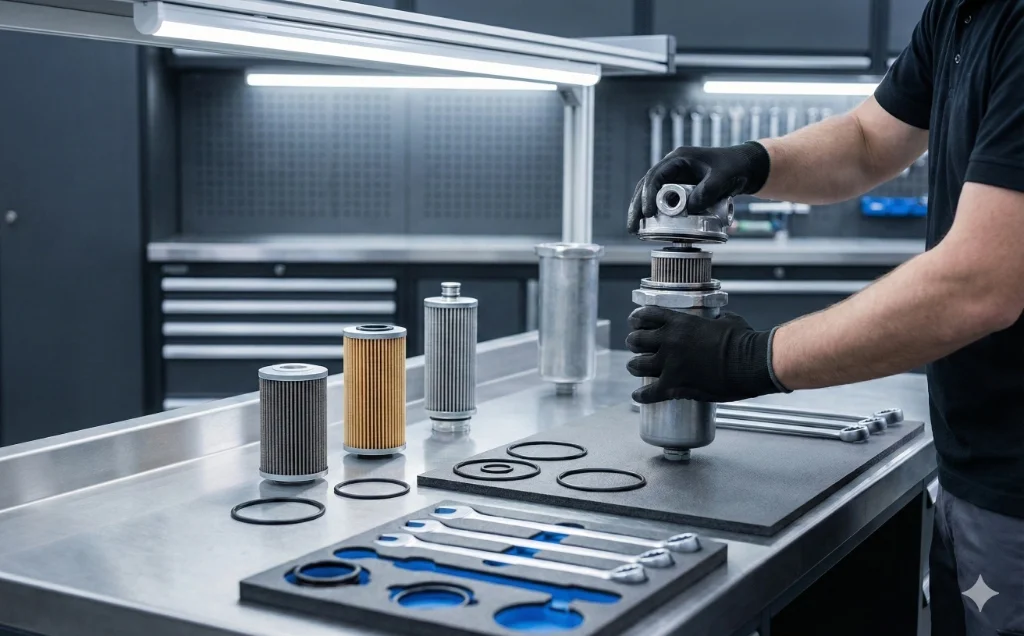
First, the system must be completely shut down, locked out, and depressurized. Before loosening the filter bowl or housing cover, the entire exterior of the filter assembly must be thoroughly cleaned with solvent and compressed air to prevent accumulated environmental dirt from falling into the open housing. Once opened, the old element should be removed carefully and inspected. An abnormally heavy accumulation of metal flakes on the old element is often the first early-warning sign of impending pump failure. The interior of the housing should be flushed and wiped with lint-free cloths.
When installing the new high-efficiency glass fiber element, always replace the associated O-rings and backup rings. Lubricate the new seals with clean hydraulic fluid to prevent tearing or rolling during reassembly. Never attempt to "clean" and reuse a disposable fiber element; compressed air will simply blow holes in the delicate fiberglass matrix, rendering it useless. Finally, ensure the housing is torqued to the manufacturer's specified values to prevent leaks and housing fatigue.