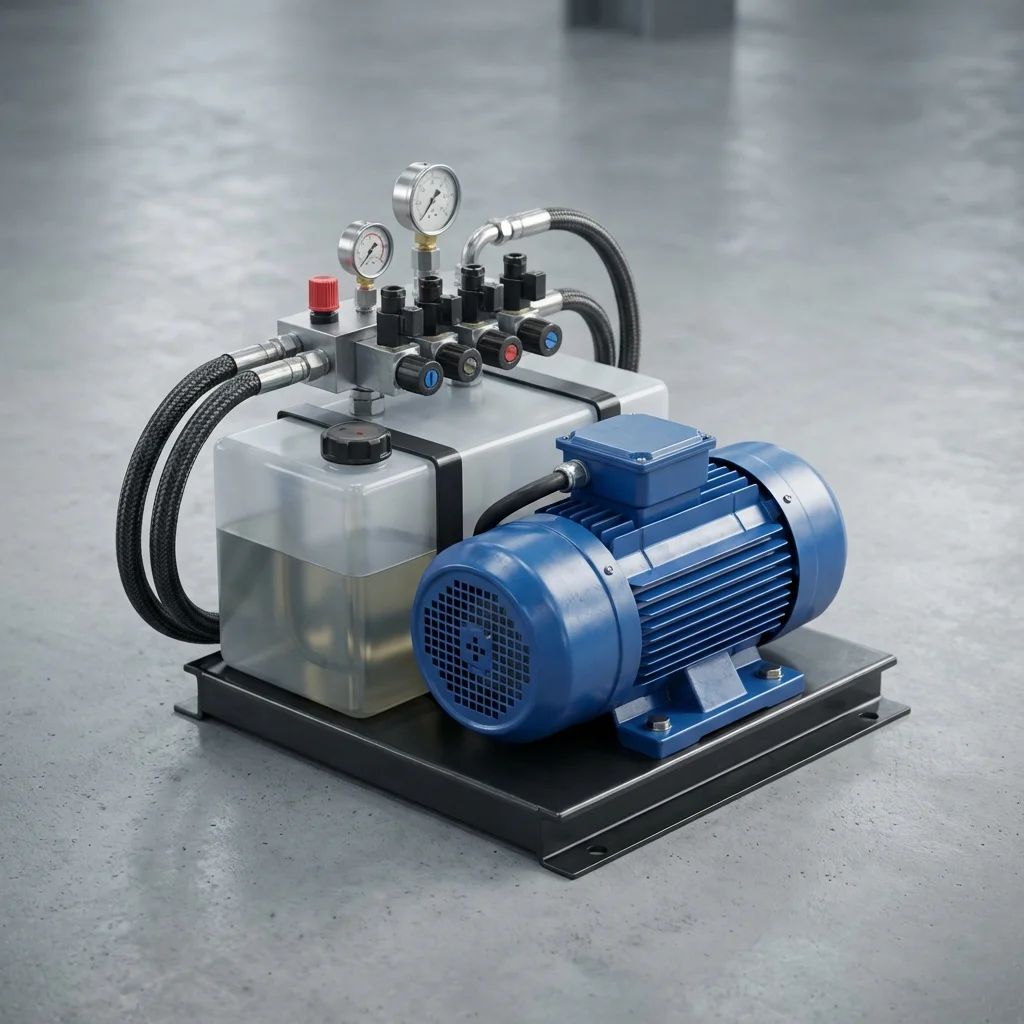
A fixed-displacement pump keeps pushing the same amount of oil regardless of whether the system needs it at that moment. The excess oil is dumped as heat through a bypass valve - and that's electricity you're paying for and wasting.
Typical Savings Range
20-30% electricity savings | Payback: 1.5-2 years
1. The Hidden Cost of Fixed-Displacement Systems
Even while the cylinder sits idle much of the time on a production line, a fixed-displacement pump keeps running at full flow. That extra energy builds up as heat, raising both cooling needs and oil aging.
1.1. The Payoff of Switching to Variable-Displacement
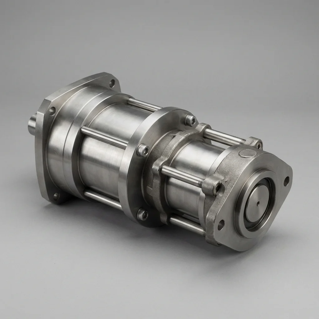
Variable-displacement pumps automatically adjust flow to system demand. On a heavily-used line, this change can deliver notable savings in electricity consumption.
| Method | Typical Savings | Payback Period |
|---|
| Variable-displacement pump | 20-30% | 1.5-2 years |
| VFD integration | 15-25% | 1-2 years |
| Filter/line maintenance | 5-10% | Within months |
- VFD Integration: adjusts pump RPM in real time to demand, saves under variable load profiles
- Heat Management: dirty filters and narrow lines create unnecessary pressure drop that turns into heat
- Energy Audit: measuring the real load profile is the only reliable way to decide the right investment
"Rather than guessing which measure will save the most, measuring the system's real load profile is the only reliable path to the right investment decision."
— BRS PROSES Engineering Team
2. BRS Proses Energy Audit
- Pressure and flow profile measurement
- Variable-displacement pump / VFD feasibility analysis
- Heat loss source detection
- Return-on-investment calculation
6. VFD & Servo-Hydraulic Pump Architecture (Power-on-Demand)
In traditional hydraulic units running with fixed-speed induction motors (1,500 RPM), the pump constantly circulates oil across relief valves during dwell, clamping, or workpiece loading phases. This wastes up to 60% of total electrical energy as rejected fluid heat.
BRS PROSES servo-hydraulic power units deploy synchronous permanent-magnet servo motors driving fixed-displacement internal gear pumps. The motor speed dynamically modulates from 0 to 3,000 RPM in milliseconds based on real-time pressure transducers. During high-pressure tonnage holding (e.g., vulcanizing press dwell), the servo motor rotates at merely 30–50 RPM just to compensate for internal cylinder leakage, dropping electrical draw from 45 kW to under 1.8 kW.
7. Hydraulic Throttling vs. Regenerative Energy Savings
Energy audits in heavy metal forming plants demonstrate immense power reclamation opportunities during rapid platen descent:
| Efficiency Strategy |
Electrical Energy Reduction |
Thermal Load Reduction |
Capital ROI Period |
| Servo-Motor Pump Drive (EFP) |
35% – 60% Reduction |
Down by 70% (Smaller coolers needed) |
12 to 18 Months |
| Regenerative Differential Circuit |
25% – 35% Faster Advance |
Recirculates exhaust rod oil to cap |
Immediate (Standard valving) |
| Waste Heat Exchanger Recovery |
Supplies plant space heating |
Captures 80% of oil thermal waste |
24 to 36 Months |
Optimizing Hydraulic Efficiency: Variable Speed Drives (VFD) & Load-Sensing Systems
Conventional hydraulic power units running standard fixed-displacement pumps at constant 1450 RPM dump excess fluid over relief valves during dwell or cooling periods, converting expensive electrical energy directly into waste heat. Modern engineering approaches utilize Servo-Hydraulic Variable Speed Pump Drives (VFD) and Post-Compensated Load-Sensing Circuits to match instantaneous hydraulic power directly to actuator demand.
1. VFD-Controlled Servo-Pumps vs Throttle Control
By modulating the electric motor RPM from 0 to 3000 RPM in milliseconds, fluid delivery matches exact process requirements. During high-pressure holding phases (such as curing in composite presses), the motor slows down to 50–150 RPM, delivering just enough flow to compensate for internal component leakage while maintaining full 250 bar pressure. This architecture reduces holding-stage energy consumption by up to 75%.
2. Hydraulic Energy Recovery through Regenerative Circuits
In rapid traverse cylinder cycles, differential regenerative circuits route fluid discharging from the rod end directly into the piston cap end rather than returning it to the tank. This doubles extension velocity without requiring a larger pump or electric motor, reducing installed motor kilowatt requirements by 30% to 45%.
Technical Field Inspection & Commissioning Protocol
Prior to signing off on any fluid power retrofit, system upgrade, or routine component overhaul, technical commissioning engineers must rigorously complete the following verification procedures to ensure full compliance with ISO machinery safety standards:
- Static Hydrostatic / Pneumatic Pressure Proof Test: Pressurize circuit to 1.5× maximum design working pressure for 15 minutes, inspecting all welded flanges and fittings for micro-weeping.
- Contamination & Fluid Particle Verification: Draw dynamic fluid samples under working temperature and confirm ISO 4406 cleanliness classes (or ISO 8573-1 air dew point classes) before activating sensitive proportional spool valves.
- Thermal Baseline Profiling: Record continuous thermal infrared scans of pump casings, valve manifold manifolds, and accumulator bodies across 4 hours of full-load production cycles to confirm proper thermal dissipation.
- Failsafe & Emergency De-energization: Verify manual LOTO isolation valves, dump valves, and accumulator vent blocks discharge trapped hydraulic/pneumatic kinetic energy to 0 bar within 2.0 seconds of emergency e-stop triggering.