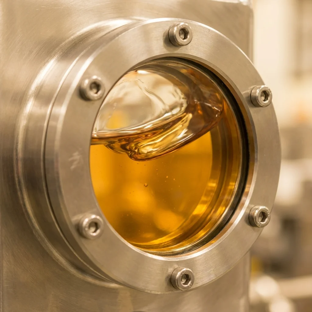
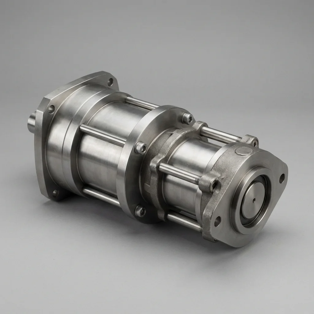
A gravel-like noise from a hydraulic pump is, more often than not, the first sign of cavitation. Ignore it and within weeks it turns into permanent damage to the pump housing.
First Sign
A metallic/gravel-like noise from the pump, growing louder with rising RPM. Continuing to run after hearing this sound raises the risk.
1. How Cavitation Forms
When pressure in the pump's suction line drops below the oil's vapor pressure, microscopic vapor bubbles form inside the oil. When these bubbles reach the high-pressure zone of the pump, they collapse suddenly and create microscopic impacts on the metal surface.
1.1. Typical Suction-Line Causes
A suction line that's too long or too narrow, a clogged suction filter, or a low reservoir level all cause suction-side pressure to drop more than it should.
- Noise: metallic/gravel-like sound, grows louder with RPM
- Pressure Fluctuation: irregularity in pump output pressure
- Temperature Rise: abnormal increase in system temperature
- Early Wear: faster-than-expected wear on the pump housing
| Measure | Area Affected | Result |
|---|
| Enlarge suction line diameter | Pressure drop | Reduces cavitation risk |
| Move filter to pressure side | Suction resistance | Protects suction pressure |
| Correct viscosity oil choice | Cold start | Improves flowability |
"Continuing to run the pump after hearing cavitation noise turns a few weeks of noise into an expensive failure requiring housing replacement."
— BRS PROSES Engineering Team
2. BRS Proses Cavitation Analysis
- On-site suction line design review
- Reservoir level and filter position check
- Oil viscosity/temperature compatibility analysis
- Pump housing revision/replacement support
6. Acoustic Diagnostics: Vaporous Cavitation vs. Gaseous Aeration
While both cavitation and aeration generate destructive knocking noises and erratic actuator movement, their underlying fluid dynamics require completely different engineering countermeasures:
- Vaporous Cavitation: Occurs when static fluid pressure drops below the oil’s vapor pressure ($P_{ ext{static}} < P_{ ext{vapor}} approx -0.3 ext{bar}$ absolute), causing volatile oil fractions to boil into vapor cavities. As bubbles transition into the high-pressure pump discharge zone, they implode at supersonic speeds, generating localized micro-jets with impact pressures exceeding 1,000 MPa and localized temperatures above 1,000°C.
- Gaseous Aeration: Occurs when mechanical air leaks into suction piping or low oil levels allow vortexing in the reservoir. Dissolved air expands into bubbles, collapsing fluid bulk modulus from 1.8 GPa down to under 0.05 GPa and turning oil milky.
7. Engineering Sizing Protocol for Cavitation-Free Suction Paths
Eliminating pump cavitation requires systematic reduction of flow resistance along the entire suction piping train:
| Suction Design Parameter |
Engineering Target Value |
Risk Mitigation Rationale |
| Fluid Velocity ($v_{ ext{suction}}$) |
0.6 m/s – 1.0 m/s maximum |
Prevents laminar friction pressure drop ($Delta P propto v^2$) |
| Inlet Vacuum Threshold |
≤ -0.20 bar (-150 mmHg gauge) |
Keeps pump inlet comfortably above vapor pressure point |
| Suction Pipe Geometry |
Straight run ≥ 5 × Pipe Diameter |
Eliminates asymmetric inlet flow vortices into pump gears/pistons |
| Suction Filtration Strategy |
125 μm wire mesh strainer (Optional) |
Never install 10 μm fine filters on suction lines; relocate to pressure/return lines |
Engineering Diagnostics: Cavitation Inception, NPSH Calculations & Micro-Dieseling
Hydraulic pump cavitation occurs when local static pressure at the pump inlet drops below the vapor pressure of the mineral oil ((P_{vapor})), causing dissolved gases to expand into vapor micro-bubbles. When these vapor bubbles enter the high-pressure discharge zone (e.g. 250 bar), they implode violently within microseconds. The localized shock waves exceed 1,000 MPa (10,000 bar) with micro-jet temperatures exceeding 1,100°C, eroding valve plates, pitting gear teeth, and contaminating the reservoir with fine metal dust.
1. Suction Line Sizing & Fluid Velocity Limits
To ensure pump inlet vacuum never exceeds 0.2 bar (-0.02 MPa gauge), suction line piping must be engineered strictly according to the continuous flow velocity equation:
v = (Q × 21.22) / d² (m/s)
• Recommended Suction Velocity: 0.6 m/s to 1.0 m/s (Absolute maximum: 1.2 m/s)
• Undersized suction hoses or high-micron clogged suction strainers drastically increase vacuum and trigger immediate acoustic cavitation.
2. Micro-Dieseling (Aeration Breakdown) Prevention
Distinct from vaporous cavitation, aeration occurs when entrained atmospheric air bubbles enter the suction port due to low reservoir levels or leaking shaft seals. Under rapid compression, the oxygen-rich air bubble combusts spontaneously through adiabatic compression ("the diesel effect"), burning adjacent oil molecules, producing blackened tar varnishes, and charring seal elastomers. Maintaining reservoir baffle residence times ((ge 2 ext{ minutes})) and vacuum de-aeration guarantees bubble release.
Technical Field Inspection & Commissioning Protocol
Prior to signing off on any fluid power retrofit, system upgrade, or routine component overhaul, technical commissioning engineers must rigorously complete the following verification procedures to ensure full compliance with ISO machinery safety standards:
- Static Hydrostatic / Pneumatic Pressure Proof Test: Pressurize circuit to 1.5× maximum design working pressure for 15 minutes, inspecting all welded flanges and fittings for micro-weeping.
- Contamination & Fluid Particle Verification: Draw dynamic fluid samples under working temperature and confirm ISO 4406 cleanliness classes (or ISO 8573-1 air dew point classes) before activating sensitive proportional spool valves.
- Thermal Baseline Profiling: Record continuous thermal infrared scans of pump casings, valve manifold manifolds, and accumulator bodies across 4 hours of full-load production cycles to confirm proper thermal dissipation.
- Failsafe & Emergency De-energization: Verify manual LOTO isolation valves, dump valves, and accumulator vent blocks discharge trapped hydraulic/pneumatic kinetic energy to 0 bar within 2.0 seconds of emergency e-stop triggering.