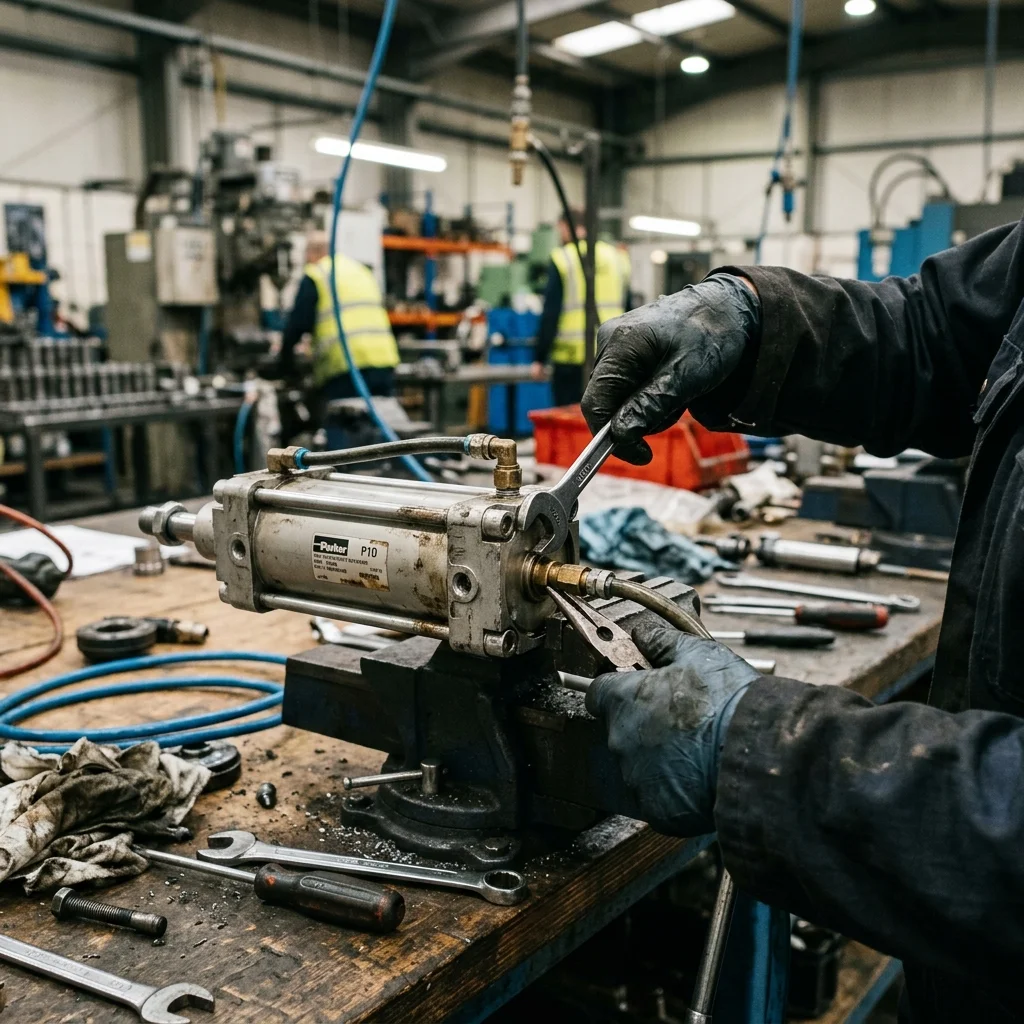
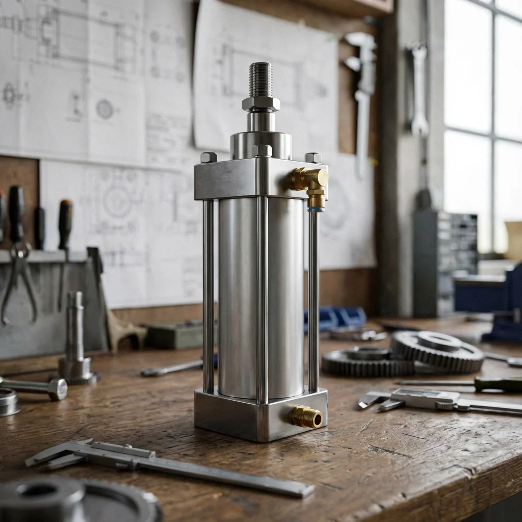
Pneumatic actuators look simple, but failure rates climb fast once maintenance is neglected. Most of the failures we see in the field don't come from complex engineering mistakes - they come from a handful of repeated maintenance habits.
1. Lubrication Mistakes
1.1. Over- or Wrong Lubrication
Some technicians set the lubricator to deliver far more oil than needed, reasoning that "more can't hurt." Excess oil builds up inside the valve, slows spool movement, and eventually swells the seals.
1.2. The Overlooked Detail on Lubrication-Free Systems
Most pneumatic actuators today ship pre-lubricated (lubricated for life) and don't want added lubrication. Adding a lubricator out of old habit introduces oil that isn't designed for those seals and can damage the elastomer structure.
2. Air Quality Neglect
- Moisture & Condensation: moisture in cooling compressed air condenses, causing corrosion and winter freeze-ups
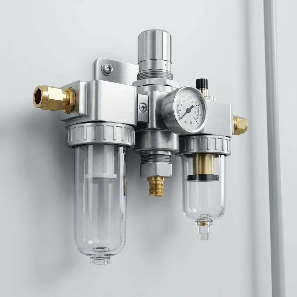
- Particle Contamination: a filter changed too late raises pressure drop, then scratches the spool surface
- Insufficient Dryer: without a quality dryer, even the most expensive actuator shows rust within months
| Maintenance Item | Recommended Interval | If Skipped |
|---|
| Filter element change | By schedule, not usage | Pressure drop, spool wear |
| Visual inspection | Monthly | Early failure signs missed |
| Valve body cleaning | Once a year | Particle buildup, seal loss |
"Seal life is largely tied to the calendar, not runtime hours; a lightly-used actuator's seals can age just as much as a heavily-used one's."
— BRS PROSES Engineering Team
3. BRS Proses Maintenance Program Support
An effective maintenance program starts from the manufacturer's FRL settings:
- Custom maintenance schedule for field teams
- FRL setting and filter replacement plan
- Lubricated/non-lubricated line consulting
- Periodic visual inspection checklist
6. Side Load & Cantilevered Radial Bending Moment Calculation
Pneumatic actuators are engineered purely to generate axial pushing or pulling vectors ($F_{ ext{axial}}$). Subjecting a standard pneumatic cylinder to unsupported cantilevered tooling weights or misalignment forces introduces severe radial side loads ($F_{ ext{radial}}$) onto the rod bearing bushing:
M_{\text{bending}} = F_{\text{radial}} \cdot (L_{\text{stroke}} + L_{\text{overhang}}) \le M_{\text{allowable}}
Even a minor side load of 150 N acting at the end of a 500 mm extended stroke induces localized contact pressures exceeding 45 MPa against the front sintered bronze bushing. This causes asymmetrical seal ovalization, immediate rod scoring, and air blowing past the wiper within weeks of commissioning. In all horizontal tooling transfers, BRS PROSES mandates external twin-guide shafts or recirculating linear profile ball rails to isolate the pneumatic piston completely from non-axial bending stresses.
7. Lubrication Chemistry: Factory Grease vs. FKM Rebuild Guidelines
Most modern ISO 15552 pneumatic cylinders are pre-lubricated at the factory with high-viscosity synthetic PTFE-based lithium greases designed for 10 million maintenance-free cycles. Introducing aggressive mineral mist lubrication through airline lubricators washes away this tenacious factory grease film. If the central plant lubricator subsequently runs dry, the cylinder experiences severe dry friction and seal destruction within hours.
| Maintenance Failure Mode |
Underlying Physical Cause |
Engineered Corrective Measure |
| Excessive Airline Lubrication |
Oil emulsion pooling in low piping legs and silencers |
Adopt non-lubricated ISO Class 1.4.1 dry air standards |
| Chemical Cleaner Ingress |
Caustic washdowns degrading standard polyurethane wipers |
Upgrade to metal-cased FKM (Viton) scraper seals + AISI 316 scraper rings |
| End-Cap Cushion Screws Closed |
Trapped cushion air stalls piston before reaching full stroke |
Calibrate adjustable cushion needle valves under full operational speed |
Advanced Failure Analysis: Mechanical Side-Loading, Over-Lubrication & Piston Scoring
Over 65% of premature pneumatic cylinder retirements are traceable to improper mechanical installation rather than component manufacturing defects. Understanding the mechanics of non-axial force vectors and chemical seal degradation is crucial for maintaining zero-failure automated production lines.
1. Radial Side-Loading: The Number One Cylinder Killer
Standard pneumatic cylinders are designed solely to transmit axial pushing and pulling forces. When external tooling, misaligned machine slides, or gravity introduce transverse lateral loads onto the rod, the bronze or PTFE rod bearing bushing experiences severe edge-loading. This causes ovalization of the bearing, uneven wear on the polyurethane wiper seal, and deep horizontal scoring across the chrome-plated piston rod. Solution: Integrate linear guide units or spherical floating rod alignment couplers (ISO 8139).
2. The Danger of Over-Lubrication & Incompatible Oils
Modern pneumatic actuators are pre-lubricated during assembly with high-performance synthetic PTFE greases engineered for lifetime operation without airline lubricators. Adding an inline oil lubricator washes away this factory grease. If the lubricator subsequently runs dry, the cylinder will operate completely unlubricated, leading to immediate seal blistering and friction-induced stick-slip. Furthermore, using motor oil or transmission fluid causes rapid swelling and disintegration of NBR/FKM seals.
Technical Field Inspection & Commissioning Protocol
Prior to signing off on any fluid power retrofit, system upgrade, or routine component overhaul, technical commissioning engineers must rigorously complete the following verification procedures to ensure full compliance with ISO machinery safety standards:
- Static Hydrostatic / Pneumatic Pressure Proof Test: Pressurize circuit to 1.5× maximum design working pressure for 15 minutes, inspecting all welded flanges and fittings for micro-weeping.
- Contamination & Fluid Particle Verification: Draw dynamic fluid samples under working temperature and confirm ISO 4406 cleanliness classes (or ISO 8573-1 air dew point classes) before activating sensitive proportional spool valves.
- Thermal Baseline Profiling: Record continuous thermal infrared scans of pump casings, valve manifold manifolds, and accumulator bodies across 4 hours of full-load production cycles to confirm proper thermal dissipation.
- Failsafe & Emergency De-energization: Verify manual LOTO isolation valves, dump valves, and accumulator vent blocks discharge trapped hydraulic/pneumatic kinetic energy to 0 bar within 2.0 seconds of emergency e-stop triggering.